The right gear reducer is not the most powerful option or the most popular model. It is the unit whose torque capacity, reduction ratio, efficiency profile, and mounting configuration align precisely with the mechanical demands, duty cycle, and spatial constraints of your specific application. This guide walks through the selection variables that determine fit—and the consequences of getting them wrong.
Key Takeaways
- Gear reducers trade motor speed for torque — the reduction ratio sets exactly how much speed drops and how much torque multiplies at the output shaft
- Four primary types (worm, planetary, helical inline, helical-bevel) each target different combinations of ratio range, efficiency, and available space
- Selection comes down to six factors: output torque, reduction ratio, thermal efficiency, shaft orientation, AGMA service factor, and total cost of ownership
- Unplanned downtime costs $10,000 to $500,000 per hour—undersizing to save upfront cost is a high-risk strategy
What Is a Gear Reducer?
A gear reducer is a mechanical transmission device that uses a series of meshing gears to reduce motor output speed while proportionally increasing torque at the driven shaft. Also called a gearbox or gear unit, the device sits between a motor and a load, translating high-speed, low-torque rotation into the slower, higher-torque motion required by conveyors, mixers, extruders, and positioning systems.
The gear reduction ratio (or transmission ratio) defines the relationship between input and output shaft speeds. It is calculated as the ratio of input RPM to output RPM — or equivalently, the ratio of output teeth to input teeth across the gear train. A 10:1 reduction ratio means the output shaft rotates once for every 10 input rotations, and the output torque is multiplied by approximately 10 (minus efficiency losses).
The fundamental equation governing reducer performance is:
Output Torque = Input Torque × Reduction Ratio × Efficiency
Efficiency is not a secondary concern — it directly determines how much input power reaches the load versus how much is lost as heat.
Types of Gear Reducers
Worm Gear Reducers
Worm gear reducers use a worm (threaded screw) meshing with a worm wheel to achieve right-angle input/output configuration. They are compact, capable of high reduction ratios (up to 100:1 in a single stage), and naturally resistant to back-driving at higher ratios due to sliding contact between worm and wheel.
That same sliding contact creates significant friction. Efficiency drops drastically at high ratios — ranging from 80% down to 40% at ratios near 50:1, meaning a large portion of input horsepower converts to heat rather than output power.
Worm gears are best suited for intermittent-duty, low-power applications where compactness and right-angle orientation outweigh efficiency concerns.
Critical note: The "self-locking" behavior of worm gears at high ratios is unreliable. Machinery's Handbook warns that static friction changes with vibration and rubbing speed make irreversible worm gearing impracticable for safety applications. Always specify mechanical brakes for hoists, lifts, and inclined conveyors — never rely on worm gear back-drive resistance alone.
Planetary (Epicyclic) Reducers
Planetary reducers distribute load across multiple planet gears orbiting a central sun gear while meshing with an outer ring gear. This load-sharing design delivers exceptional torque density in a compact, coaxial package, with efficiency ranging from 95–98% per stage, low backlash, and high stiffness.
Planetary units excel in high-acceleration applications (robotics, servo-driven axes) and high-torque, low-speed applications (rotary furnaces, machine tools). Single-stage ratios typically range from 3:1 to 12:1. The trade-off: planetary reducers are more complex and costly than worm types.
Helical Inline and Helical-Bevel Reducers
Helical gears use angled teeth that mesh with a rolling rather than sliding action, minimizing friction. Helical inline reducers achieve up to 98.5% efficiency per stage with parallel shaft orientation, making them ideal for high-power, continuous-duty applications where energy cost matters.
Helical-bevel reducers add a right-angle stage (bevel gears) for directional change, offering higher torque capacity than worm reducers at comparable sizes while maintaining efficiency in the mid-90% range. Both types are back-drivable, so applications requiring load-holding must incorporate brakes or backstops.
Multi-Stage and Hybrid Arrangements
For very high reduction ratios or elevated torque capacity within tight space constraints, multi-stage configurations (helical-helical, helical-worm) and specialized designs (double-enveloping worm) are available. These options are worth exploring for demanding applications where standard single-stage units fall short — and understanding these trade-offs is the foundation for every selection decision covered in the sections ahead.
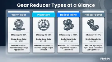
Reducer Type Comparison at a Glance
| Type | Typical Efficiency | Single-Stage Ratio Range | Best For |
|---|---|---|---|
| Worm Gear | 40–80% | 5:1 to 100:1 | Compact, intermittent-duty, right-angle |
| Planetary | 95–98% | 3:1 to 12:1 | High torque density, servo/robotics |
| Helical Inline | Up to 98.5% | 1.25:1 to 8:1 | High-power, continuous-duty, parallel shaft |
| Helical-Bevel | 93–97% | 5:1 to 200:1 (multi-stage) | Right-angle, high torque, continuous-duty |
Key Factors to Consider When Choosing a Gear Reducer
Reducer selection is not a single-variable problem. The right choice emerges from evaluating interconnected mechanical, operational, and environmental parameters—all of which tie directly to reliability, energy cost, and maintenance intervals.
Required Output Torque
Torque is the primary sizing variable. The reducer must be rated to handle the maximum torque demanded by the load at the output shaft, expressed in newton-meters (N·m) or pound-feet (lb·ft). Undersizing torque capacity is the leading cause of premature gear failure.
Manufacturers publish minimum and maximum torque ratings for each product. To verify fit:
- Calculate required output torque from load characteristics: Torque = Force × Moment Arm
- Apply the AGMA service factor (discussed below) to account for duty cycle and shock loads
- Compare the adjusted torque requirement against catalog ratings
If the required torque exceeds the reducer's rating, gears and bearings face strain beyond design limits, leading to surface wear, lubricant breakdown, and early failure.
Speed Reduction Ratio
The reduction ratio defines how much the input speed (motor RPM) must be divided to achieve the required output RPM. This ratio also determines the torque multiplication factor. Misaligning ratio with application needs results in either excess heat buildup (ratio too low, motor running too fast) or inadequate speed at the driven device (ratio too high).
Reduction ratio requirements vary widely by industry:
- High-ratio needs (40:1 to 100:1): Conveyors, winches, hoists → worm or multi-stage reducers
- Moderate ratios with high efficiency (5:1 to 20:1): Packaging lines, robotics, CNC machines → helical or planetary types
- Low ratios (3:1 to 10:1): High-speed, high-power applications → helical inline
To calculate required ratio: Reduction Ratio = Motor Input RPM ÷ Desired Output RPM
Efficiency and Thermal Performance
Efficiency directly affects operating energy costs and heat generation. A less efficient reducer wastes input power as heat, which can require external cooling, shorten lubricant life, and accelerate wear.
Efficiency comparison by type:
- Helical inline: Up to 98.5% per stage
- Helical-bevel / Planetary: 94-97% per stage
- Worm (low ratios, ~5:1): Up to 90%
- Worm (high ratios, ~50:1): 40-80%
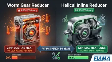
For continuous-duty applications, efficiency differences translate directly into operating cost. A 10 HP motor driving a worm reducer at 80% efficiency wastes 2 HP as heat. Over 8,000 operating hours per year at $0.10/kWh, that's roughly $1,200 in wasted energy annually—enough to justify a higher-efficiency helical unit within 3-5 years.
Thermal performance becomes critical in continuous-duty or confined mounting spaces. A reducer's thermal rating—the input horsepower limit for continuous duty without overheating—must equal or exceed the motor's input power.
If operating power exceeds thermal capacity, oil degrades rapidly and failure follows quickly. Always verify the thermal rating alongside the mechanical torque rating.
Shaft Orientation and Mounting Configuration
Shaft geometry must match the spatial layout of the drive system. The three primary orientations are:
- Orthogonal (right-angle): Worm and helical-bevel reducers
- Coaxial (inline): Planetary and helical inline reducers
- Parallel offset: Helical inline reducers
Output shaft type (solid vs. hollow bore) and mounting interface (flange, foot, torque arm) further constrain selection. Worm reducers typically offer the widest variety of mounting configurations, while planetary and helical inline products are more limited. Locking in orientation early prevents costly redesigns once other components are specified around it.
AGMA Service Factor and Environmental Conditions
With shaft geometry confirmed, the next step is sizing for real operating conditions—not just peak torque. The AGMA service factor is the ratio of the reducer's rated capacity to the application's required capacity. It accounts for:
- Duty cycle: Hours per day of operation
- Load type: Uniform, moderate shock, heavy shock, extreme shock
- Equipment type: Conveyors, mixers, crushers, etc.
AGMA publishes service factor tables by gear type and application. Selecting a reducer without applying the correct service factor is one of the most common engineering mistakes.
Example AGMA service factors:
| Duration Per Day | Uniform Load | Moderate Shock | Heavy Shock |
|---|---|---|---|
| Less than 3 hours | 1.00 | 1.00 | 1.25 |
| 3-10 hours | 1.00 | 1.25 | 1.50 |
| Over 10 hours | 1.25 | 1.50 | 1.75 |
If your application requires 100 N·m at the output shaft, runs 12 hours per day, and experiences moderate shock loads, the service factor is 1.50. You must specify a reducer rated for at least 150 N·m to ensure adequate capacity.

Environmental multipliers apply for extreme temperatures, chemical exposure, high vibration, or frequent start/stop cycles. In these cases, work directly with a manufacturer or distributor's engineering team rather than selecting off a standard catalog.
Total Cost of Ownership
Initial purchase price is only one component of total cost. Factor in:
- Efficiency losses: Energy cost over the product's 10-15 year life
- Lubrication and maintenance intervals: Labor and downtime
- Downtime risk: Cost of premature failure
Unplanned industrial downtime costs $10,000 to $500,000+ per hour. At those rates, one failure event from an undersized reducer wipes out whatever you saved on purchase price—often many times over.
TCO as the decision tiebreaker: A worm reducer may be the right choice for intermittent-duty, low-power applications. A higher-efficiency helical or planetary unit often pays for itself in energy savings and reduced maintenance over 3-5 years in continuous-duty, high-horsepower installations.
How FIAMA US Can Help You Choose the Right Gear Reducer
FIAMA US is a distributor of Italian-made industrial components staffed entirely by engineers, not commissioned salespeople. Every reducer recommendation is driven by application fit, not quota pressure.
FIAMA's engineering team works directly with customers to map torque requirements, duty cycles, environmental constraints, and budget parameters to the right reducer specification. That means fewer mismatches and less unplanned downtime.
Key differentiators:
- ISO 9001-certified, Italian-manufactured products with consistent dimensional tolerances
- Short lead times supported by an extensive, growing US inventory
- Technical support from engineers with hands-on application knowledge
- A focused product line that allows genuine expertise across every SKU carried
Whether you need a compact worm reducer for an intermittent-duty conveyor or a high-efficiency helical unit for a continuous-duty packaging line, FIAMA's team can guide you through torque calculations, service factor application, and thermal rating verification—helping you avoid the costly mistakes that lead to premature failure.
Conclusion
A mismatched gear reducer doesn't fail quietly. It drives unplanned downtime, accelerated wear, and repair costs that routinely run into six figures per incident. The right selection, by contrast, extends service life, cuts energy waste, and keeps production on schedule.
The selection framework covers six core decisions:
- Calculate required output torque at the application load
- Determine the reduction ratio needed for target output speed
- Apply the correct AGMA service factor for your duty cycle
- Verify thermal rating for continuous-duty applications
- Match shaft orientation to your spatial constraints
- Evaluate total cost of ownership across the product's service life
Gear reducer selection is not a one-time act. As production requirements evolve, duty cycles change, or new environments are introduced, the suitability of the installed reducer should be periodically reviewed against current operating parameters. What fit the application three years ago may no longer be adequate—or may now be over-engineered.
Frequently Asked Questions
What is the difference between a gear reducer and a gearbox?
The terms are used interchangeably in industrial contexts. Both describe a mechanical device that uses gears to reduce rotational speed and increase output torque between a motor and a driven load. AGMA standards and major manufacturers use both terms synonymously.
How do I calculate the gear reduction ratio I need?
Divide the motor's input RPM by the desired output RPM. For example, if your motor runs at 1,800 RPM and you need 180 RPM at the output shaft, the required reduction ratio is 10:1. This ratio also determines torque multiplication—output torque equals input torque multiplied by the ratio and efficiency.
What is a service factor and why does it matter when selecting a gear reducer?
The AGMA service factor is a multiplier applied to required torque or horsepower to account for duty cycle, load shock, and operating hours. Uniform-load applications running 8 hours per day typically require 1.00, while heavy-shock applications running 12+ hours per day require 1.75 or higher. Skipping this step is a leading cause of premature reducer failure.
Which type of gear reducer is most energy efficient?
Helical inline reducers offer the highest efficiency (up to 98.5% per stage), followed by helical-bevel and planetary types (94-97%). Worm gear reducers are the least efficient at high reduction ratios, dropping to 40-80% due to sliding contact between worm and wheel.
Can one gear reducer type work across multiple different applications?
No single reducer type suits every application. The right choice depends on torque, speed, efficiency, environmental conditions, and space constraints—a worm reducer that works well on an intermittent-duty conveyor will waste significant energy in a continuous-duty packaging line.
How often should a gear reducer be serviced or replaced?
Most manufacturers recommend lubricant inspection and changes every 2,500 to 5,000 operating hours for continuous-duty applications. Worn seals, elevated temperature, increased noise, or vibration are early warning signs that service or replacement is needed.