In modern industrial operations, even small inaccuracies in measurement can ripple into major operational issues. Equipment downtime, inconsistent product quality, and increased scrap rates are common challenges when measurement systems fail to deliver precise feedback. For procurement managers, plant heads, and engineers, relying on traditional or imprecise measurement methods can make it difficult to maintain stable processes and meet strict production standards.
Displacement transducers offer a practical solution by providing accurate, real-time measurement of movement or position. When properly integrated, they can help reduce downtime, improve yield stability, and enhance overall equipment performance.
In fact, the displacement sensor market is projected to reach USD 2.5 billion by 2033, growing at a CAGR of 9.2%. Choosing the right transducer and understanding how it operates ensures your team can respond quickly to variations, maintain consistent quality, and make data-driven decisions that optimize operations.
This guide breaks down their working principles, sensor types, key selection parameters, and common challenges.
At a Glance:
Displacement transducers convert motion into electrical signals, allowing precise monitoring and control of equipment.
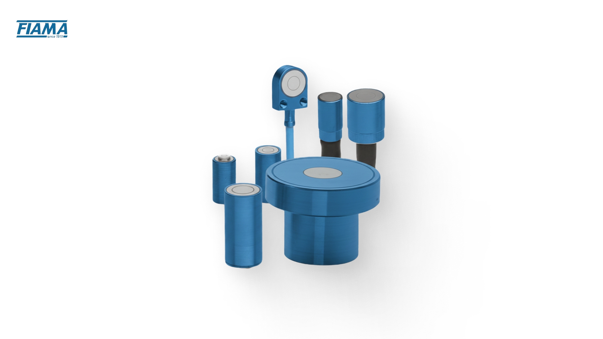
They are available in various types, like LVDTs, potentiometric, magnetic, capacitive, optical, and draw-wire sensors for different industrial needs.
Choosing the right transducer depends on range, accuracy, resolution, response time, environment, and output type to deliver reliable performance.
Common challenges include alignment issues, signal noise, environmental effects, wear in contact sensors, and calibration drift.
What is a Displacement Transducer?
A displacement transducer is a sensor that measures linear or angular movement and converts it into a useful electrical or mechanical signal. These devices support machine accuracy, repeatability, and equipment health monitoring. Their value increases wherever motion directly affects quality, output, or safety.
Here’s why they matter in modern equipment:
Precision Measurement: Helps monitor exact positions of machinery components, reducing errors and improving equipment uptime. For example, in automated packaging lines, it ensures that filling nozzles and conveyor positions are precise.
Process Control: Provides real-time feedback for automated systems, supporting consistent production and enhancing throughput and lead time stability. In CNC machining, displacement transducers track tool movement to maintain precise cuts.
Quality Assurance: Minimizes scrap rates and ensures reliable output by detecting deviations in motion or alignment early, critical in food processing or metal fabrication.
Versatility: Suitable for a wide range of industries, including food, packaging, wood, metal, and semiconductor production, for both mechanical and automation applications.
By integrating displacement transducers, plants can better manage performance metrics, optimize machine operations, and maintain consistent product quality. Next, let's understand what components make accurate measurement possible.
Key Functional Elements of Displacement Transducers
A displacement transducer includes mechanical, electrical, and sensing components that convert motion into signals. Knowing these elements helps your team evaluate durability, signal quality, and long-term maintenance needs more effectively.
Sensing Element
This is the core component that detects movement and converts it into a measurable signal. Its design determines accuracy, repeatability, and maintenance frequency.
Depending on the technology, the sensing element may be:
Conductive track (potentiometric transducers): Simple and cost-effective, but may require periodic cleaning or replacement in dusty environments.
Magnetic scale (magnetic encoders): Robust in high-vibration and dusty conditions; less frequent calibration is needed.
Optical code disk (optical encoders): High-resolution but sensitive to contaminants, requiring protective housings or filters.
Coil structure (LVDTs): Long-lasting and highly repeatable; suited for applications with constant motion cycles.
Draw-wire mechanism (string potentiometers): Flexible and easy to integrate for large-range measurements; cables may need occasional inspection for wear.
Choosing the right sensing element directly influences maintenance schedules. Plants that prioritize continuous uptime will favor magnetic or LVDT-based solutions, which reduce inspection frequency and signal drift risk.
Signal Conditioning Electronics
Signal conditioning electronics process raw signals from the sensing element, converting them into stable outputs compatible with PLCs or control systems. They ensure:
Noise reduction in electrically congested environments, preventing false readings from motors, drives, or welding equipment.
Stable output despite vibration or mechanical shocks, which is critical in packaging lines, metal presses, or automated conveyors.
Seamless compatibility with PLCs, supports smooth integration with existing control systems.
Smooth transitions, eliminating sudden jumps in readings that could trigger unnecessary alarms or halt production.
In high-speed plants, unstable or noisy signals can disrupt PLC logic, causing unplanned downtime or affecting throughput. Investing in robust signal conditioning improves overall lead time stability and process consistency.
3. Mechanical Housing and Construction
The housing protects the sensing element and electronics from environmental hazards. Its design affects durability, washdown capability, and long-term reliability.
Materials: Stainless steel, anodized aluminum, or reinforced polymers resist dust, moisture, chemicals, and heat.
Environmental protection: Properly sealed housings allow safe operation in washdown zones, wet processes, or dusty assembly areas.
Mounting stability: A rigid housing supports precise alignment and reduces drift caused by vibration or thermal expansion.
In food, pharma, or packaging plants, housings that tolerate high-pressure cleaning or chemical exposure reduce unplanned maintenance and minimize downtime. Robust construction also ensures accurate readings even under vibration or mechanical stress, directly supporting equipment uptime and yield consistency.
In the following section, let's look at how these components work together to generate precise motion data.
How a Displacement Transducer Works?
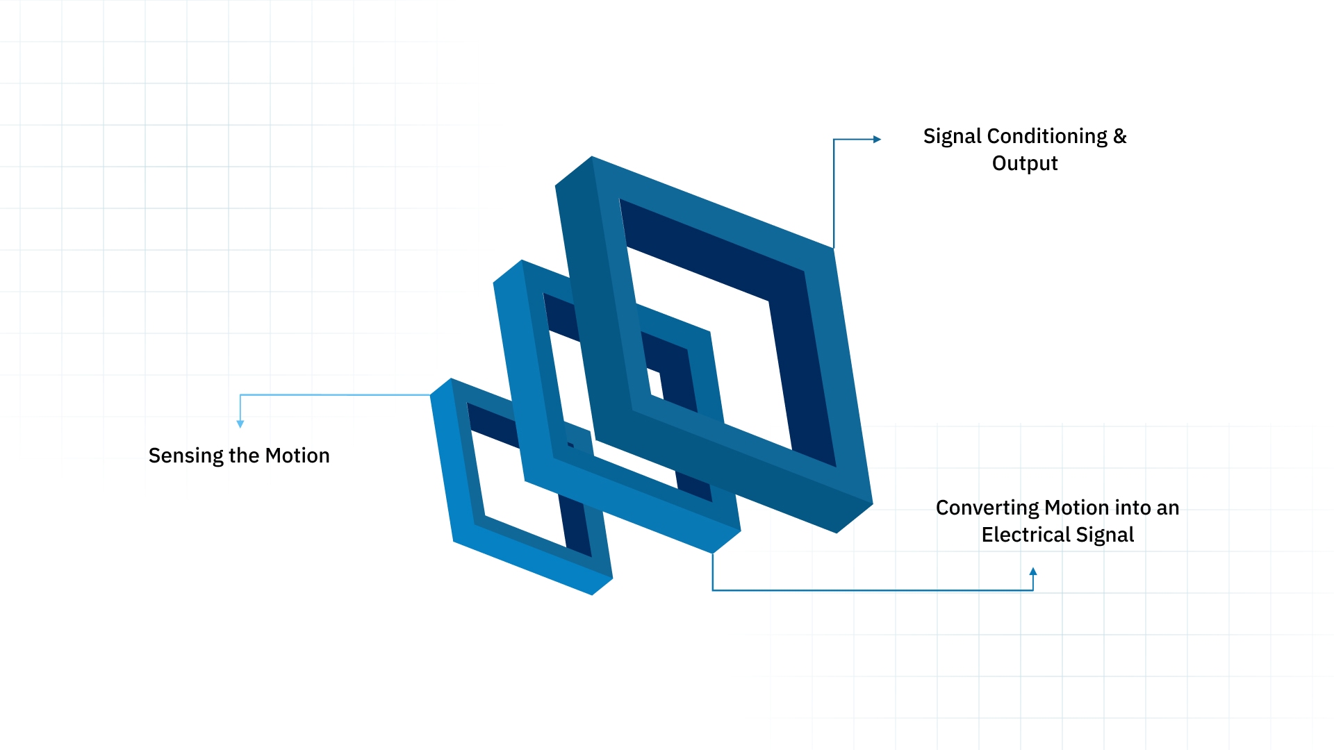
Displacement transducers measure motion by converting mechanical movement into an electrical signal that control systems can interpret. The process works in three key steps:
Sensing the Motion
The first step detects the movement of the target object. Depending on the type of transducer, this can involve:
Linear movement: A core moves inside coils in an LVDT, or a cable extends in a draw-wire sensor.
Rotary movement: A shaft or angular element rotates inside an RVDT.
Non-contact sensing: Magnetic, capacitive, or eddy-current sensors detect displacement without physical contact.
The sensor captures actual mechanical motion accurately, providing a reliable starting point for measurement.
Converting Motion into an Electrical Signal
Once motion is detected, the transducer converts it into an electrical representation. Different transducer types achieve this using various principles:
LVDT (Inductive): Core movement alters magnetic flux in coils, producing a voltage proportional to displacement.
Potentiometric/Draw-wire: Movement changes resistance in a potentiometer or encoder, generating a corresponding electrical output.
Eddy current: Motion changes the magnetic field in a conductor, producing an electrical signal that varies with displacement.
Capacitive: Displacement alters capacitance between two surfaces, which is then measured and converted.
This step ensures the mechanical movement becomes a measurable, interpretable signal.
Signal Conditioning and Output
The raw electrical signal often requires refinement before it can be used:
Amplification: Improves weak signals for better accuracy and resolution.
Filtering: Removes noise caused by vibrations, EMI, or other environmental factors.
Conversion: Transforms the signal into a usable format, like voltage (0–10 V), current (4–20 mA), or digital outputs for PLCs and data acquisition systems.
Proper signal conditioning ensures the transducer delivers stable, reliable, and accurate readings that integrate seamlessly into automated systems or monitoring setups.
Now that the working principles are covered, it’s easier to compare different types of displacement transducers used across industrial equipment.
Types of Displacement Transducers
There are several kinds of displacement transducers, each suited for different applications. The choice depends on required precision, environmental conditions, and mechanical constraints.
Below, we’ll break down the most common types used in manufacturing, automation, and process industries.
Linear Variable Differential Transformers (LVDTs)
LVDTs are widely used for high-precision linear displacement measurement. They operate without direct electrical contact, making them ideal for harsh or high-cycle industrial environments.
Key Features:
Non-contact operation: The moving core does not touch coils, reducing wear and maintenance needs.
High accuracy: Provides precise linear displacement readings, supporting critical industrial measurements.
Durable design: Resistant to dust, moisture, and temperature variations, suitable for continuous operation.
Ideal use-case scenario: Critical hydraulic testing or servo system applications requiring consistent, precise readings.
Avoid when: Space is extremely tight and compact sensors are needed, or very long-range measurement is required.
Potentiometric Displacement Transducers
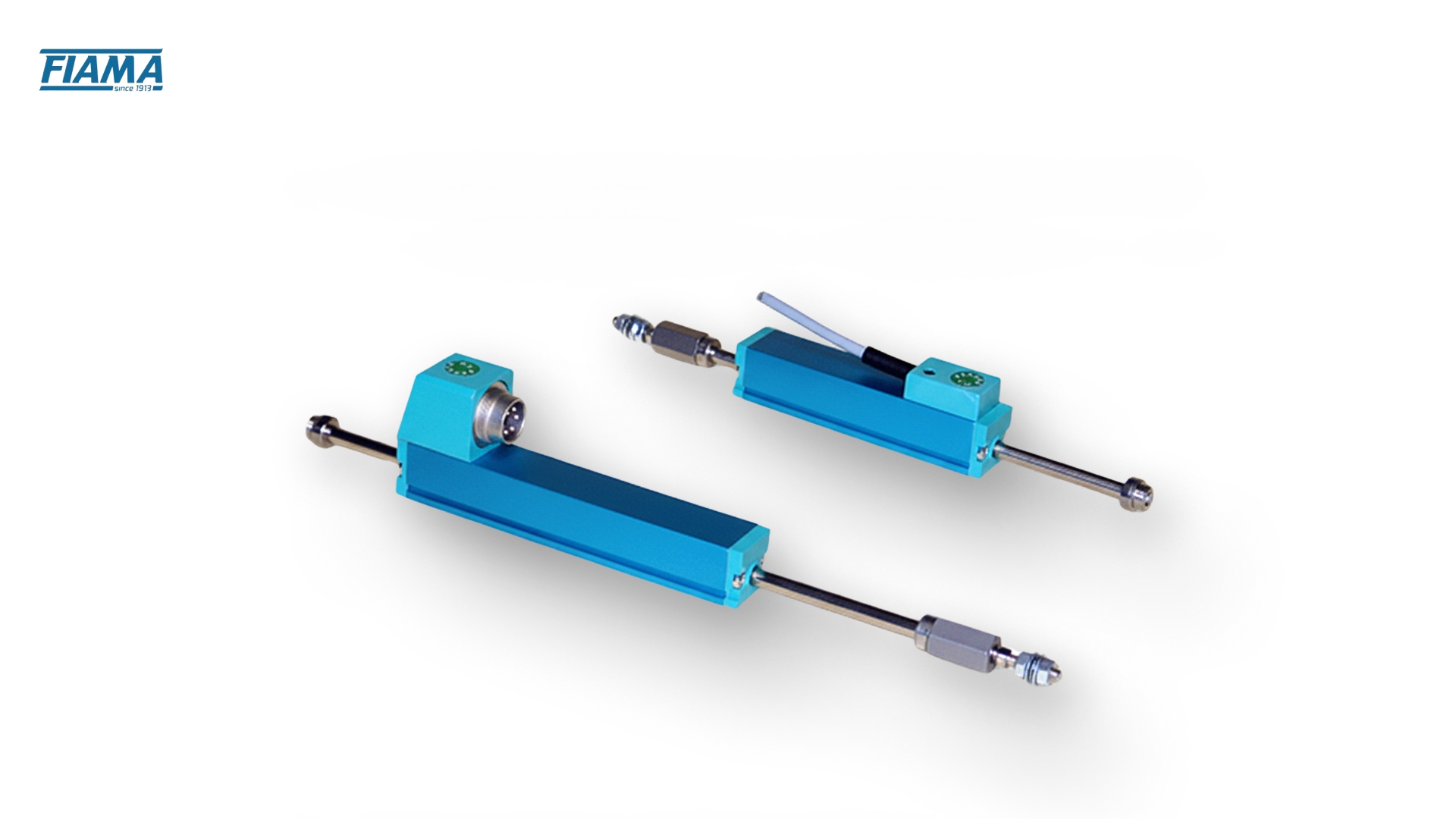
A sliding contact (wiper) moves along a resistive track in potentiometric transducers to measure displacement precisely. They are simple, cost-effective, and versatile, making them common in applications with moderate precision requirements.
Key Features:
Direct analog output: Provides straightforward voltage signals corresponding to position, which is easy to integrate with control systems.
Compact and versatile: Can be customized for linear or rotary displacement in tight mechanical setups.
Durable for moderate use: Suitable for industrial machinery where extreme precision is not critical but reliability matters.
For example, Fiama offers linear potentiometer transducers (measuring lengths from 25 mm to 900 mm) for applications needing simple, economical position feedback.
Ideal use-case scenario: General industrial measurement and process monitoring tasks with moderate precision requirements.
Avoid when: High-speed or highly dynamic measurement is required.
Magnetic Displacement Transducers
Magnetic transducers detect displacement by tracking variations in magnetic fields. They are non-contact, resistant to environmental contaminants, and perform well in harsh industrial conditions.
Key Features:
Non-contact operation: Minimizes wear and maintenance, which is critical in dusty, oily, or high-vibration environments.
Robust design: Can operate under high temperatures, moisture, or electromagnetic interference without loss of accuracy.
Flexible range options: Can be adapted for linear or rotary measurement, from small adjustments to larger strokes.
Fiama’s magnetic encoders offer a compact, modular design with waterproof, contamination‑resistant, non‑contact operation, suitable for all industrial applications, up to linear measuring lengths of 50 metres.
Ideal use-case scenario: Packaging or automotive applications in challenging environments.
Avoid when: Extremely high-precision sub-micron measurements are required.
Capacitive Displacement Transducers
Capacitive sensors detect changes in capacitance as plates move, measuring displacement with high sensitivity. They are highly sensitive and suitable for micro-precision applications where tiny variations must be detected.
Key Features:
High resolution: Can detect sub-micron movements, making them suitable for precision engineering and laboratory applications.
Non-contact measurement: Reduces mechanical wear, providing stable performance over time.
Fast response time: Useful for dynamic measurements in high-speed machinery.
Ideal use-case scenario: Semiconductor manufacturing or electronics assembly requiring micro-level precision.
Avoid when: Large-scale or heavy industrial displacement measurement is needed.
Optical Displacement Transducers
Optical sensors track displacement by monitoring changes in light reflection, interruption, or interference patterns, giving precise real-time feedback. They provide high-speed, high-resolution measurements.
Key Features:
Extreme precision: Capable of sub-micron resolution for detailed motion control and monitoring.
Fast response: Suitable for applications requiring rapid measurement and feedback.
Non-contact operation: Reduces wear and maintenance while enabling measurement in delicate setups.
Ideal use-case scenario: Robotics or semiconductor inspection systems requiring high-speed, high-precision measurement.
Avoid when: Harsh industrial environments with dust or vibration could interfere with optical signals.
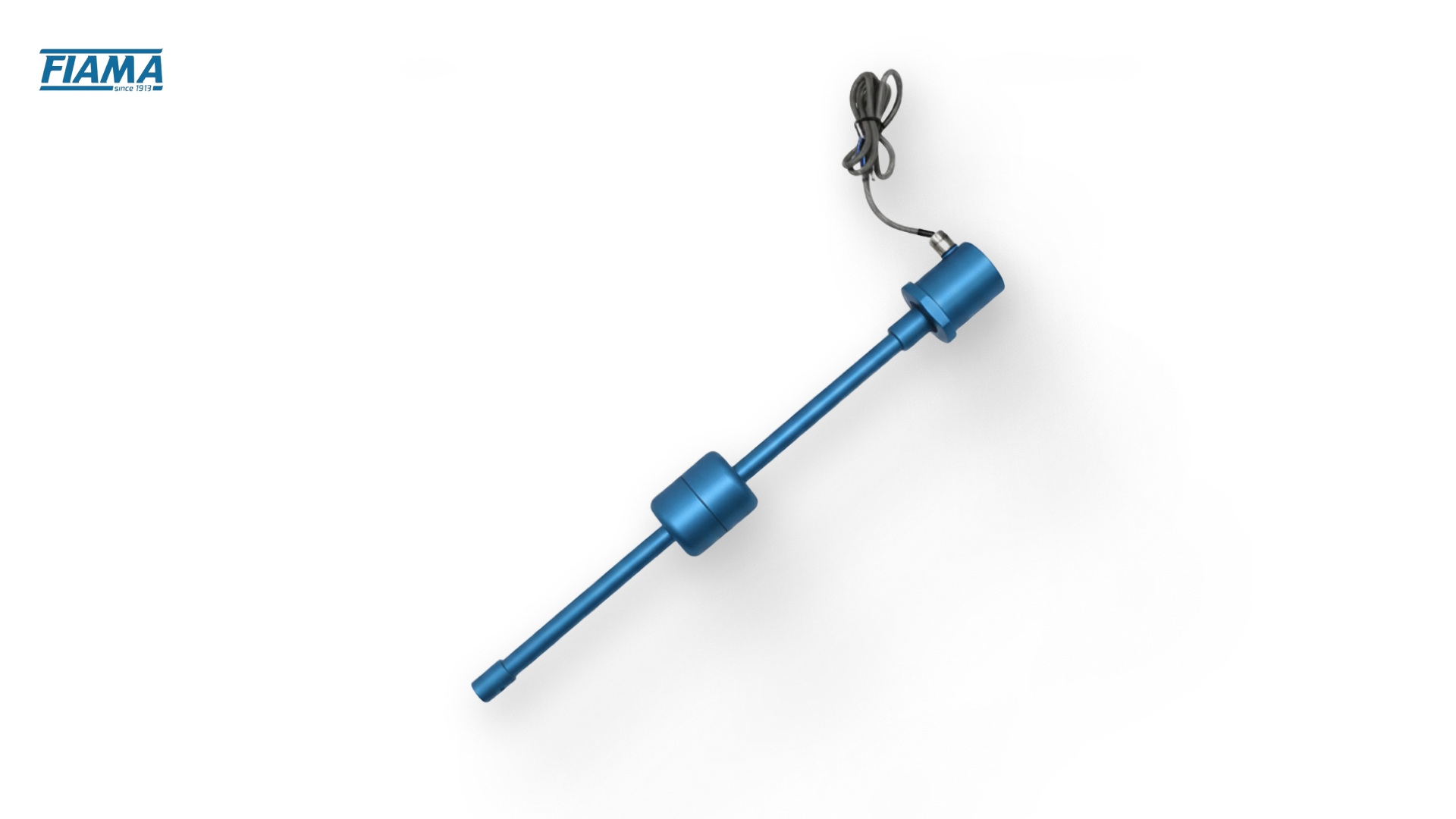
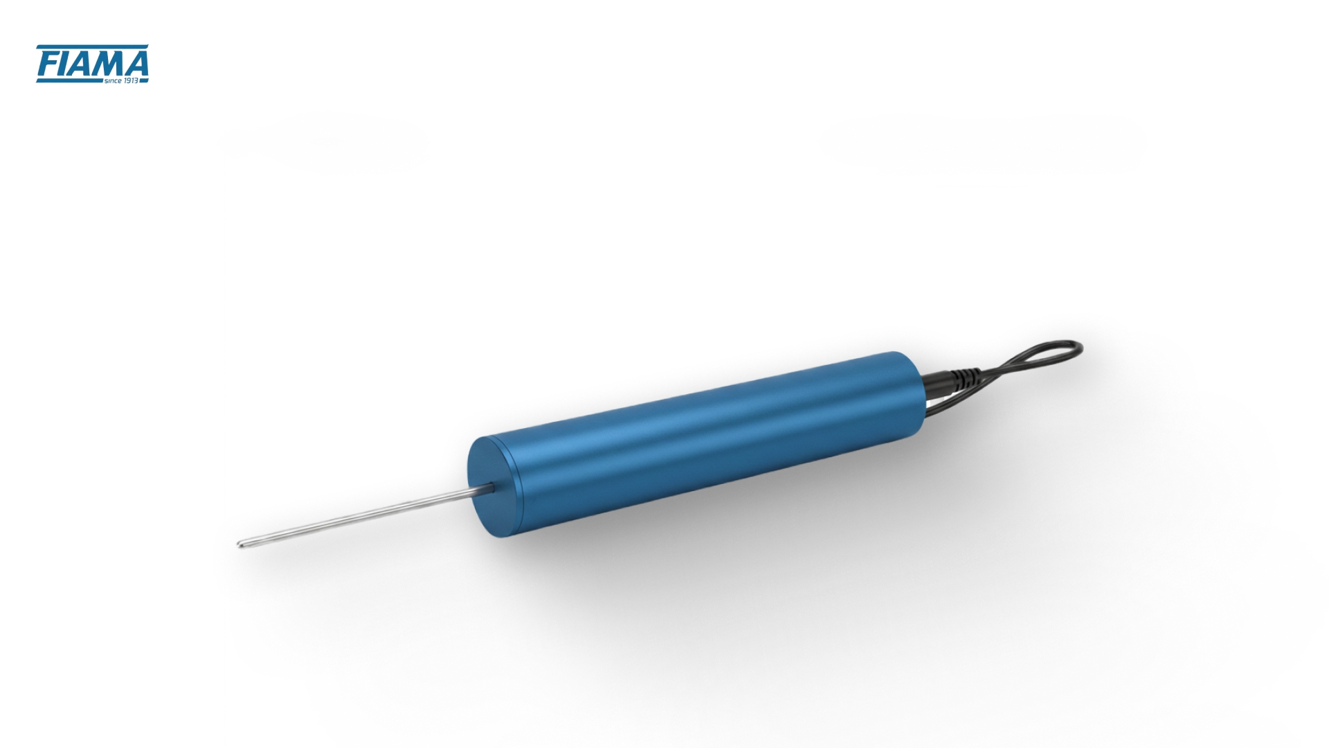
Draw Wire (String Potentiometer) Sensors

Draw wire sensors measure linear displacement via a retractable cable connected to a pulley and sensor mechanism. They are versatile and adaptable to long travel distances.
Key Features:
Long-range measurement: Can handle distances often exceeding what LVDTs or potentiometers manage.
Flexible installation: Cables can be routed around obstacles, making them practical for large equipment.
Durable design: Engineered for industrial environments with mechanical robustness.
Fiama offers a wide range of draw wire encoders, with measuring lengths from 50 mm up to 12,000 mm, available with potentiometer, analog (0‑10 V / 4‑20 mA), or encoder outputs.
Ideal use-case scenario: Measuring the displacement of large machinery components or mobile equipment.
Avoid when: Space constraints prevent cable routing, or very high-speed measurement is needed.
In the next section, let's discuss how to select the right displacement transducer.
Key Parameters to Consider When Selecting a Displacement Transducer
Selecting the right displacement transducer requires evaluating multiple factors to ensure accurate measurement, reliability, and compatibility with your application. Here are the key parameters to consider:
Measurement Range: Choose a transducer with a range that fully covers the expected motion. Using a sensor with too narrow a range can saturate the signal, while an overly large range may reduce measurement resolution.
Resolution and Accuracy: High-resolution sensors detect small changes in displacement, which is critical for precision applications. Accurate sensors closely reflect the actual movement, directly impacting quality control and process reliability.
Response Time and Speed: Fast-responding transducers are essential for high-speed applications, such as automated assembly or dynamic testing, to capture real-time changes without lag or data loss.
Environmental Compatibility: Consider operating temperature, humidity, vibration, and exposure to dust or chemicals. Choosing sensors rated for harsh environments reduces downtime and requires less maintenance.
Output Signal Type: Evaluate whether the transducer provides analog or digital output and ensure it aligns with your control system or data acquisition setup. Ensuring the right signal type simplifies integration and avoids unnecessary complications.
Mounting and Installation Flexibility: Look for options that allow secure, easy installation without affecting the machine operation. Flexible mounting options minimize mechanical stress and keep the sensor performing reliably over time.
Long-Term Stability and Drift: Choose sensors that maintain consistent performance over time. Low drift keeps recalibration frequency low and supports continuous, accurate monitoring.
Environmental Suitability and Supplier Risk: Ensure the transducer is compatible with your plant environment and sourced from a reliable supplier. This reduces downtime, mitigates maintenance issues, and protects against disruptions in component availability.
Cost vs. Application Needs: While high-precision sensors can be more expensive, aligning cost with performance ensures you invest in the right level of accuracy and reliability for your process.
Common Challenges in Using Displacement Transducers
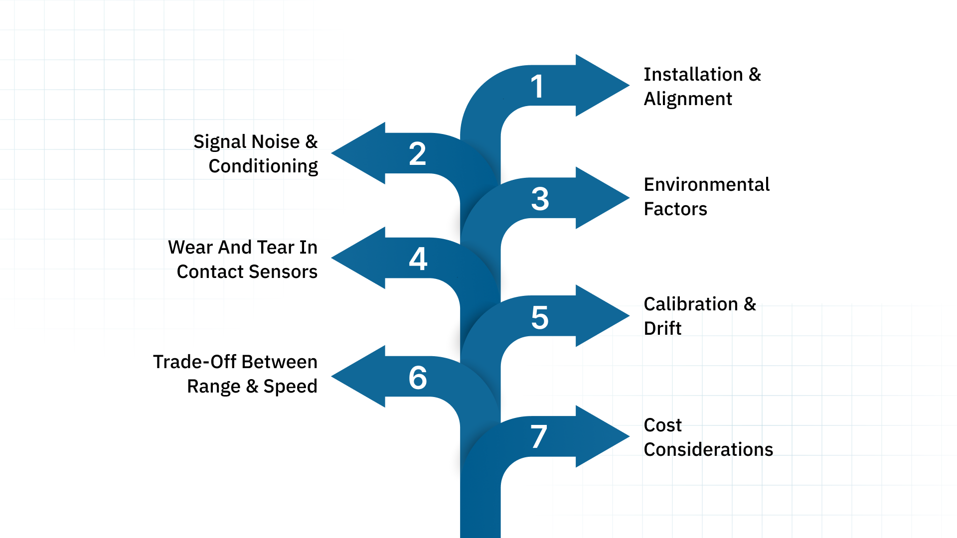
Even reliable sensors face challenges in demanding industrial environments. Understanding these helps procurement managers, engineers, and operations leaders make informed decisions and minimize performance risks.
Installation & Alignment: Misaligned sensors, cores, or cables can cause inaccurate readings. Careful mechanical mounting and alignment ensure accurate measurements.
Signal Noise & Conditioning: Raw outputs may be weak or susceptible to electromagnetic interference. Applying proper filtering, amplification, and synchronous detection keeps signals clean and stable.
Environmental Factors: Temperature variations, vibration, dust, or moisture can impact sensor performance. Selecting non-contact or sealed designs helps sensors handle harsh industrial environments effectively.
Wear and Tear in Contact Sensors: Mechanical contact (e.g., potentiometers or draw-wire sensors) can degrade over time due to friction, spring fatigue, or cable wear. Regular inspection and maintenance maintain long-term accuracy.
Calibration and Drift: Sensors can gradually drift from their original calibration due to mechanical fatigue or thermal cycling. Performing regular checks and recalibration keeps readings precise.
Trade-Off Between Range and Speed: High-speed sensors may have shorter ranges, while long-range sensors may respond more slowly. Choosing the right balance ensures accurate and responsive measurements.
Cost Considerations: High-precision or non-contact sensors can be expensive. Balancing upfront cost with long-term performance and maintenance needs prevents overspending.
To handle these challenges effectively, many manufacturers prefer working with a partner that understands measurement applications in detail.
How Fiama Supports High-Precision Displacement Measurement?
Fiama specializes in delivering high-quality, Italian-engineered measurement components and practical OEM solutions tailored to industrial needs. Their deep expertise and engineering support help operations teams integrate sensors effectively.
Here’s how we can help:
Practical OEM Engineering Support: Fiama’s team of degreed engineers provides hands-on guidance for selecting and integrating displacement transducers. Their advice is tailored to your equipment and processes, helping reduce downtime and potential measurement mismatches.
High-Quality Italian-Made Products: All Fiama products are designed and manufactured in Parma, Italy, with over 100 years of experience. Components such as potentiometer transducers, magnetic encoder systems, and draw wire encoders feature metal housings for durability and longevity in food, packaging, wood, and automation applications.
Customizable Stroke Lengths: Fiama offers displacement transducers with configurable stroke lengths and tailored product variants to match specific operational needs. This helps optimise throughput, minimise scrap, and stabilise lead times.
In-House R&D and Manufacturing: All design, testing, and production happen in-house at the Parma factory. This end-to-end control allows Fiama to deliver products adapted to complex industrial applications and reduces supplier risk.
Support Through Edmar Metric LLC: Customers in the U.S. and broader Americas benefit from localized support and product expertise via Edmar Metric LLC, ensuring faster response times, engineering guidance, and application-specific solutions.
Fiama’s combination of practical engineering support, configurable designs, and durable Italian-made components helps operations teams simplify integration and achieve smoother, more predictable displacement measurement outcomes.
Conclusion
Displacement transducers play a foundational role in modern manufacturing. They capture the motion data that keeps machines aligned, tooling accurate, and processes repeatable. Understanding how they work and choosing the right type helps operations reduce downtime, maintain predictable cycle times, and support quality requirements.
Working with a knowledgeable partner helps teams evaluate sensor behavior, integration requirements, and long-term reliability. FIAMA supports these needs with engineered solutions, durable construction, and strong application expertise.
If you want guidance on selecting the right displacement transducer or need support with integration, reach out to us today.
FAQs
What is the difference between an active and passive displacement transducer?
Active transducers generate their own electrical signal in response to displacement, requiring no external power. Passive transducers, however, need an external power source to produce an output signal proportional to displacement, making them dependent on a separate excitation voltage.
How does electromagnetic interference affect displacement transducers?
Electromagnetic interference (EMI) can introduce noise or distort the output signal of a displacement transducer, reducing measurement accuracy. Sensitive transducers may require shielding, proper grounding, or signal filtering to maintain reliable readings in environments with high electrical or magnetic interference.
What are the maintenance requirements for displacement transducers?
Maintenance involves periodic inspection for physical damage, cleaning moving parts, checking electrical connections, and verifying output accuracy. Calibration should be performed regularly to ensure precision. Proper storage, environmental protection, and avoiding exposure to extreme temperatures or vibrations also extend the transducer’s operational life.
What is the difference between a transducer and a transmitter?
A transducer converts a physical parameter (like displacement) into an electrical signal, while a transmitter amplifies, conditions, and sends this signal to a remote display or control system. Essentially, transducers sense, and transmitters communicate, often working together in measurement systems.
How is a displacement transducer calibrated?
Calibration involves comparing the transducer’s output to known displacement standards, adjusting its signal to match reference values, and documenting accuracy. This ensures precise measurement, compensates for drift, and maintains reliability in industrial applications, often using specialized calibration equipment or test rigs.