Introduction
Spec sheets, supplier catalogs, and technical drawings routinely use "gear reducer" and "gearbox" interchangeably — sometimes to describe the exact same product. For engineers and procurement teams in food processing, pharmaceutical, and packaging applications, that ambiguity creates real specification risk.
Understanding where these terms diverge matters when the component drives torque output, motor compatibility, and maintenance cycles.
Misreading a datasheet due to terminology confusion can translate directly into wrong-sized components, incompatible motor pairings, and reduced system efficiency. In pharmaceutical manufacturing alone, unplanned downtime costs between $1 million and $5 million per hour — correct specification isn't optional. This guide cuts through the terminology overlap so engineers and buyers can specify the right component with confidence.
Key Takeaways
- A gearbox is a broad mechanical term for a housing containing gear sets that transmit power—capable of increasing speed, decreasing speed, or multiplying torque
- Gear reducers are a specific gearbox type built to reduce output speed and multiply torque
- The two terms are used interchangeably in most industrial contexts; gear ratio, torque rating, and mounting configuration are what actually matter
- When specifying either, nail down: required gear ratio, output torque, input RPM, mounting type, and duty cycle
Gear Reducer vs. Gearbox: Quick Comparison
| Aspect | Gearbox | Gear Reducer |
|---|---|---|
| Function | Transmits mechanical power between shafts; can reduce speed, increase speed, or maintain a fixed ratio | Reduces rotational speed from input; increases output torque |
| Design Structure | Enclosed housing containing a gear train (spur, helical, bevel, worm, or planetary); motor may or may not be included | Enclosed gear train (spur, helical, bevel, worm, or planetary); always configured for speed reduction from a motor input |
| Speed/Torque Behavior | Output depends on configuration — may increase speed in automotive or wind turbine applications | Output speed always lower than input; output torque always higher (accounting for efficiency losses) |
| Common Industries | Automotive transmissions, wind turbines, heavy machinery, marine propulsion | Industrial automation, conveyors, packaging machinery, food processing, pharmaceutical equipment, robotics |
| Terminology Usage | More common in automotive, heavy equipment, and European manufacturing | Preferred term in North American industrial automation and manufacturing |
What Is a Gearbox?
A gearbox is an enclosed mechanical assembly of gears and shafts that transmits rotational power from a driving source (typically a motor) to a driven load. The International Organization for Standardization (ISO 22109:2020) formally defines it as a "self-contained gear unit for torque/thrust/speed/orientation change." It's a broad mechanical term encompassing any device that modifies speed, torque, or direction using interlocking gears.
The key mechanical principle: gear ratio determines the relationship between input and output speed and torque. A gearbox can step speed down (more common in manufacturing) or step it up (as in wind turbines or high-speed spindles) depending on which gear drives the system.
Main types of gearboxes in industrial applications:
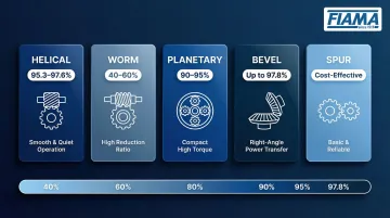
- Helical gearboxes — Smooth, quiet operation with 95.3-97.6% efficiency; ideal for high-load applications
- Worm gearboxes — High reduction ratios with self-locking capability; efficiency ranges from 40-60% due to sliding friction
- Planetary gearboxes — Compact, high torque density (90-95% efficiency); excellent for precision applications
- Bevel gearboxes — Change shaft direction by 90°; efficiency up to 97.8%
- Spur gearboxes — Simple, cost-effective design for straightforward power transmission
A gearbox does not inherently include a motor—it is the mechanical stage only, serving as a standalone power transmission device between a motor and driven load.
Use Cases of a Gearbox
Gearboxes appear across diverse industries where variable speed profiles or bidirectional power flow matter:
- Automotive drivetrains — Multi-speed transmissions for varying road conditions
- Wind energy — Speed-increasing gearboxes that convert slow turbine rotation to high-speed generator input
- Mining and construction equipment — Heavy-duty power transmission in harsh environments
- Marine propulsion systems — Torque conversion for ship propellers
In food processing, pharmaceutical manufacturing, packaging, and semiconductor production, gearboxes appear in conveyors, filling machines, rotary indexers, and robotic end-of-arm tooling. Helical and planetary units dominate these applications due to their precision and low backlash characteristics.
What Is a Gear Reducer?
A gear reducer (also called a speed reducer) is a mechanical device—typically a gearbox or gearbox-motor combination—specifically configured to reduce the rotational speed of a motor's output shaft while proportionally increasing available output torque. The term "gear reducer" implies directional intent: speed always decreases, torque always increases.
How a Gear Reducer Works
The input shaft (connected to the motor) drives a smaller gear, which meshes with a larger gear on the output shaft. The ratio of tooth counts determines speed reduction and torque multiplication. The fundamental relationship:
Output torque = Input torque × Gear ratio × Efficiency
For example, a 10:1 gear ratio means output speed is 1/10th of input speed, and output torque is theoretically 10× the input torque, minus efficiency losses (typically 5-15% depending on gear type).
Common Types of Gear Reducers
- Inline (parallel shaft) — Helical gearing delivers linear power transfer at up to 97.6% efficiency
- Right-angle — Worm or bevel-helical designs handle 90° shaft orientation; bevel-helical units reach 94–97.8% efficiency, while worm designs trade efficiency for self-locking capability
- Planetary — Compact, high-torque-density units suited for precision positioning; common in pharmaceutical packaging lines and robotic joints
Terminology Nuance
In North American industrial parlance, "gear reducer" and "gearbox" are often interchangeable. In some product catalogs and OEM specifications, however, "gear reducer" specifically refers to a combined motor-and-gearbox unit (also called a geared motor). "Gearbox," in that context, describes only the gear mechanism without the motor attached.
Always verify this distinction when reviewing manufacturer datasheets — the same term can mean different things across suppliers.
Use Cases of a Gear Reducer
Gear reducers are the standard solution where torque multiplication and speed reduction are required:
- Conveyor drives in food, beverage, and packaging lines requiring consistent low-speed, high-torque output
- Agitators and mixers in pharmaceutical and chemical processing
- Augers and feeders across agricultural and food manufacturing systems
- Semiconductor assembly equipment where minimal backlash is critical
Real-world example: In 2023, a cement facility replaced aging gearboxes with Sumitomo Cyclo 6000 Speed Reducers, correctly matching gear reduction ratios to prevent motor overload. The specification prevented ongoing equipment failure and delivered $375,000 in cost savings across initial replacements.
Gear Reducer vs. Gearbox: Key Differences and When to Use Each
In most industrial purchasing and engineering contexts, a gear reducer is simply a gearbox configured for speed reduction. The distinction becomes meaningful only in specific cases: when comparing a gearbox used for speed increase vs. speed reduction, or when one term includes the motor and the other does not.
Knowing which label applies to your application shapes how you specify the component — and which catalog you reach for first.
Functional Decision Logic
Choose a "gearbox" specification when:
- Evaluating multiple configurations (speed increase vs. reduction)
- Working in automotive or heavy machinery contexts
- Selecting a component that may serve multiple speed profiles
Choose a "gear reducer" specification when:
- Your application requires torque multiplication and speed reduction
- Specifying for industrial automation (conveyors, packaging, robotics)
- Using North American industrial catalogs with motor-gearbox integrated units
The Role of Gear Ratio
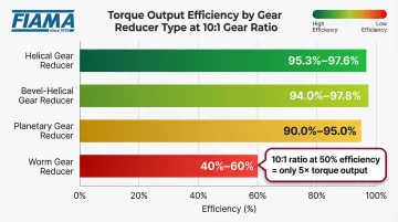
A 10:1 gear ratio means output speed is 1/10th of input speed, and output torque is (theoretically) 10× input torque. Efficiency ratings are critical when calculating actual output torque, yet they're routinely overlooked during specification:
- Helical gears: 95.3–97.6% efficiency
- Bevel-helical gears: 94.0–97.8% efficiency
- Planetary gears: 90.0–95.0% efficiency
- Worm gears: 40–60% efficiency (highly variable)
A 10:1 worm gear reducer operating at 50% efficiency delivers only 5× torque multiplication, not 10×. This gap can lead to motor overload and premature failure if not properly calculated.
Specifications That Matter More Than the Label
When selecting either component, focus on these critical parameters:
- Output torque (Nm) — Size to exceed calculated load torque; apply your service factor before finalizing
- Input speed (RPM) — Match to your motor's operating speed, not nameplate maximum
- Gear ratio — Calculated as motor RPM ÷ required output RPM
- Mounting configuration — Inline, right-angle, flange, or shaft-mounted
- Service factor — Apply 1.0–2.5 depending on shock load severity and duty cycle; undersizing here is a common failure point
- IP/ingress protection rating — Critical for food and pharma environments
- Lubrication type — NSF H1 food-grade compliance where required
Industry-Specific Selection Criteria
Food and pharmaceutical applications require additional considerations beyond mechanical specifications:
- Stainless steel housings — Corrosion resistance and sanitary design
- IP65+ or IP69K protection — Washdown capability; IP69K withstands high-pressure (80–100 bar), high-temperature (80°C) washdowns
- NSF-compliant lubricants — H1-rated for incidental food contact, compliant with FDA 21 CFR 178.3570
Once you've confirmed these parameters, the label on the catalog page matters far less than whether the unit is sized correctly for your load.
Choosing the Right Solution for Your Application
Practical Decision Checklist
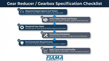
Before specifying a gear reducer or gearbox, answer these questions:
- What is the required output speed and torque? — Calculated from your load requirements
- What is the motor's rated speed and torque? — From motor nameplate or datasheet
- What is the required gear ratio? — Motor RPM ÷ output RPM
- What mounting orientation is needed? — Inline, right-angle, or shaft-mounted
- What are the environmental requirements? — Temperature range, ingress protection, lubrication type
- What is the expected duty cycle and load profile? — Uniform loads vs. shock loads, starts per hour
The Cost of Misspecification
Getting any of those answers wrong has real consequences. Misspecification—choosing the wrong gear ratio, underestimating service factor, or ignoring environmental ratings—leads to premature failure and costly downtime. Unplanned downtime costs the world's 500 largest companies approximately $1.4 trillion annually (11% of revenues). In pharmaceutical manufacturing, a single hour of downtime can cost between $1 million and $5 million.
Primary causes of gear drive failure:
- Continuous steady-state overloads from erroneous power calculations
- Improper lubrication (responsible for 43% of mechanical failures)
- Shock loading from rapid starts/stops or reversing loads
- Inadequate service factor application
The Value of Expert-Guided Selection
Working with an application engineer—rather than selecting from a general catalog—cuts specification errors, especially in food processing and pharmaceutical manufacturing.
FIAMA's application engineers — degreed, non-commissioned, and not working against quotas — focus entirely on matching the right component to your actual operating conditions. That means correct gear ratio selection, appropriate service factor, and full environmental compliance from the start.
Frequently Asked Questions
Is a gear reducer the same as a gearbox?
In most industrial contexts, yes—the terms are used interchangeably. Technically, a gear reducer is a specific type of gearbox configured to reduce speed and increase torque, while "gearbox" is the broader term that can also describe speed-increasing or variable-speed configurations.
What is the purpose of a gear reducer?
A gear reducer reduces the rotational speed of a motor's output while multiplying available torque, allowing a standard high-speed motor to drive low-speed, high-torque applications like conveyors, mixers, and packaging equipment.
What is the difference between a gear reducer and a speed reducer?
These terms are synonymous in practice. Both describe a device that reduces input speed and increases output torque. The difference is framing: "speed reducer" emphasizes the functional outcome, while "gear reducer" specifies that gears (rather than belts, chains, or pulleys) do the work.
What are the most common types of gear reducers used in manufacturing?
The four most widely used types are:
- Worm gear reducers — high reduction ratios, compact footprint
- Helical gear reducers — high efficiency, smooth and quiet operation
- Planetary reducers — high torque density, precision positioning
- Right-angle bevel-helical reducers — direction change with efficiency up to 97.8%
How do I select the right gear ratio for my application?
The gear ratio is determined by dividing the motor's output speed (RPM) by the required output shaft speed. The selected ratio must also account for output torque requirements, motor torque rating, and a service factor for load characteristics — uniform loads use 1.0, while shock loads can push that factor to 2.5.
When should I use a gear reducer instead of a direct-drive motor?
Use a gear reducer when a standard motor runs at much higher RPM than the application needs, when more torque is required than the motor can deliver alone, or when precise low-RPM speed control is critical. This covers the majority of conveyor, mixer, and robotic drive applications.