In high-precision industries like food and beverage, pharmaceuticals, and packaging, maintaining stable throughput and accurate positioning in automated systems is a constant challenge. Engineers and plant managers often face difficulties ensuring that machines operate with exact repeatability, especially when rotary encoder feedback is inconsistent or misinterpreted. Misaligned components, delayed responses, or signal errors can disrupt production schedules, increase scrap, and create unplanned downtime.
Using precise rotary encoder pulses can help reduce these inefficiencies. By delivering accurate and reliable position feedback, operations leaders and engineers can reduce misalignment issues, improve process repeatability, and make informed decisions about maintenance schedules.
With the global rotary encoder market expected to reach around $4.3 billion by 2033, it’s clear that more industries are relying on these pulse-based systems to manage performance and maintain consistent output. In this blog, we’ll explore what rotary encoder pulses are, their key specifications like PPR and resolution, discuss how to calculate and select the right encoder, and outline common challenges.
At a Glance:
Rotary encoder pulses convert shaft rotation into electrical signals that enable machines to measure position, speed, and direction, directly impacting motion control and process stability.
PPR, CPR, and resolution define how finely an encoder tracks movement, shaping positioning detail, repeatability, and overall system performance.
Encoder types, incremental, absolute, magnetic, optical, and capacitive, affect achievable resolution and are selected based on application needs, environmental conditions, and precision requirements.
Factors such as mechanical alignment, electrical noise, temperature, vibration, and control system compatibility affect pulse accuracy, so engineers must actively select, install, and maintain encoders properly for reliable operation.
What Are Rotary Encoder Pulses?
Rotary encoder pulses are electrical signals generated when the encoder shaft rotates. These pulses allow control systems to calculate position, speed, and direction. The cleaner and more accurate these pulses are, the more reliably a machine can track motion and maintain stable throughput, alignment, and positioning.
In automation systems, like CNC machines, robotics, and conveyor controls, the precision of these pulses directly affects repeatability, stability, and overall system performance.
How Rotary Encoders Generate Signals?
Encoders convert shaft rotation into electrical pulses using optical, magnetic, or mechanical sensing. Each pulse represents a small increment of movement, and the total number of pulses defines how finely the system can measure rotation.
Here’s how the signal generation typically works:
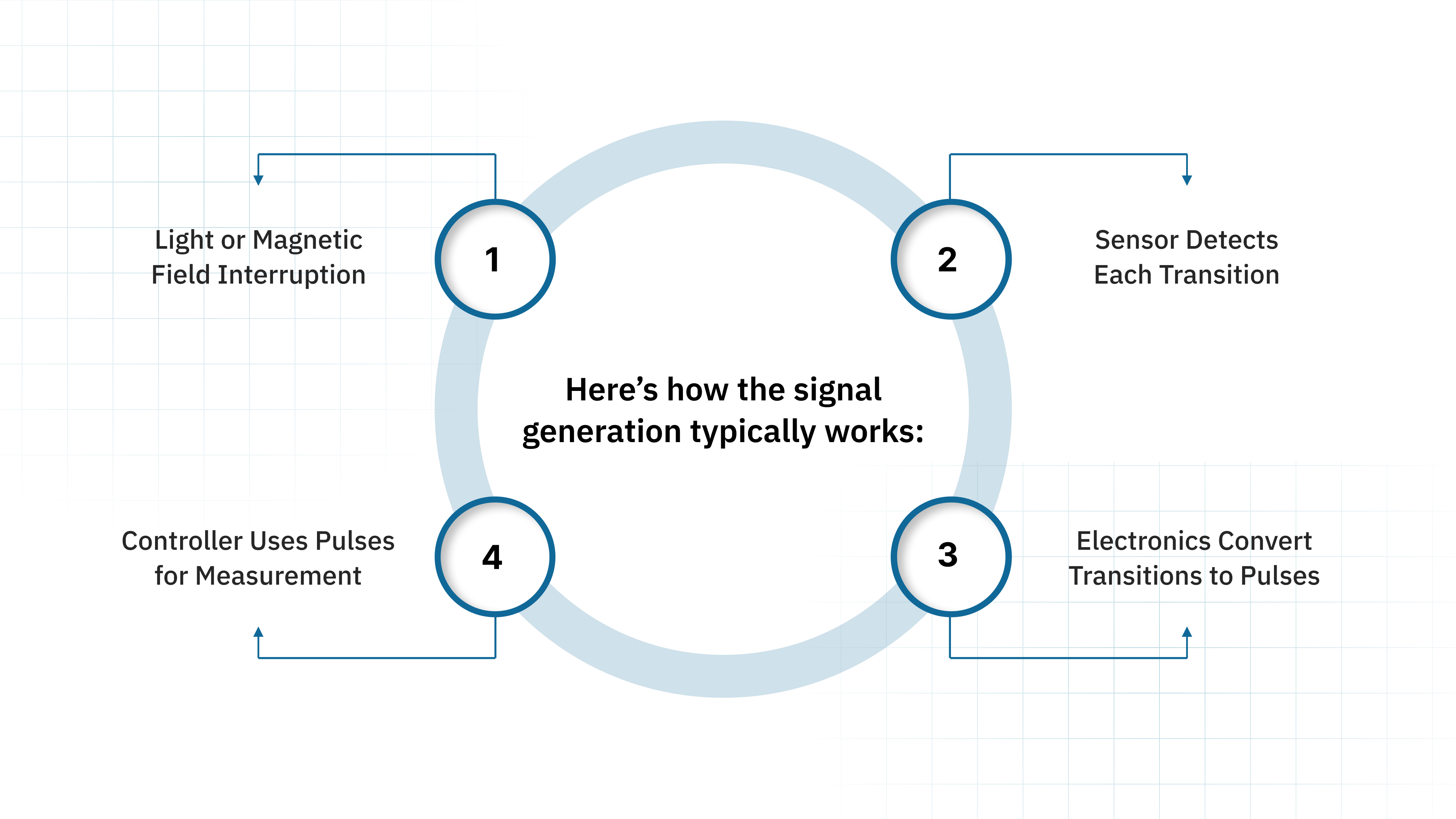
Light or Magnetic Field Interruption: As the encoder shaft rotates, it moves a disk patterned with lines (optical) or magnetic poles (magnetic). A sensor reads these patterns as variations in light or magnetic flux. Every interruption creates a detectable change.
Sensor Detects Each Transition: When the pattern on the disk passes the sensing area, the sensor detects each transition; light-to-dark, north-to-south, or voltage variations, depending on sensor type. Each transition represents a potential pulse.
Electronics Convert Transitions to Pulses: These transitions are processed by the encoder’s internal circuitry, which converts the raw physical changes into clean, square-wave electrical pulses that a controller can reliably interpret.
Controller Uses Pulses for Measurement: The output pulses are sent to a PLC, microcontroller, or motion drive. From here, the system calculates speed (pulse frequency), direction (phase shift), or position (pulse count), enabling accurate motion feedback.
Key Signal Types You’ll Encounter
Rotary encoders typically output more than one signal channel. These channels work together to deliver direction, reference, and high-resolution motion information.
The key signal types include:
Quadrature signals (A and B): Two square-wave signals offset by 90° that allow the controller to read both movement and direction. This offset allows controllers to determine whether the shaft is moving clockwise or counter-clockwise while counting pulses for position feedback.
Index (Z) pulse: A single pulse emitted once per full revolution. This reference pulse helps machines establish a repeatable “home” point, improving startup alignment, calibration routines, and cycle accuracy.
Choosing the right signal type depends on your application requirements, such as equipment uptime, downtime reduction, and the level of precision needed. Next, let’s move into the specifications, PPR, CPR, and resolution, which determine how finely an encoder can measure movement.
PPR, CPR, and Resolution: What’s the Difference?
Understanding the encoder terminology helps ensure the encoder you choose delivers the precision your application needs. Each metric affects positioning accuracy, cycle stability, and how well your control system interprets rotary encoder pulses.
PPR (Pulses per Revolution)
PPR defines how many electrical pulses the encoder outputs for one full shaft rotation. It determines how finely the encoder can break down a mechanical movement into electrical signals, directly influencing positioning accuracy.
Pulse Count: Higher PPR generates finer position increments, which support tighter motion control in applications like indexing or cutting.
Speed Consideration: More pulses increase the processing load on your controller, especially at high RPM.
Mechanical Fit: PPR must align with screw pitch, gear ratios, or belt movement to maintain consistent positional accuracy.
A correct PPR value helps balance precision and processing efficiency.
CPR (Counts per Revolution)
CPR represents the total number of counts an encoder provides per revolution when decoding all signal transitions. Most incremental encoders use quadrature signals, giving four counts per pulse and significantly increasing effective measurement detail.
Quadrature Output: By using rising and falling edges of both A and B channels, CPR increases measurement resolution without changing the encoder’s mechanical design.
Position Detail: Higher CPR helps detect smaller positional changes, which supports stable throughput in systems requiring precise speed or phase synchronization.
System Integration: CPR requirements must match the motion controller's capability to avoid missed counts during high-speed operation.
CPR is essential when you need higher measurement resolution from the same encoder footprint, allowing better performance without additional hardware complexity.
Resolution
Resolution defines the smallest change in position the system can detect. Systems typically express resolution in degrees per count for rotary setups, or in linear distance for systems using mechanical translation (e.g., leadscrews or gear ratios).
Positional Precision: Higher resolution allows the equipment to detect smaller incremental movements, improving alignment accuracy in cutting, filling, or inspection tasks.
Effect on Process Stability: Better resolution helps maintain repeatability across production cycles, which supports yield consistency and reduces rework or scrap.
Application Matching: The required resolution varies widely by process; for example, servo-controlled axes in CNC machining need much finer resolution than basic conveyors or material handling systems.
Choosing the right resolution prevents over-specification and ensures the encoder meets performance needs without adding unnecessary cost or complexity.
Together, these metrics provide a clear picture of how well an encoder can support reliable, stable, and precise motion control across industrial applications. In the next section, let’s see how to calculate encoder resolution in practical scenarios.
How to Calculate Rotary Encoder Resolution?
Encoder resolution is a measure of how finely the system can detect motion. It is calculated based on PPR and the mechanical setup of the system.
Let's see how to calculate this through an example:
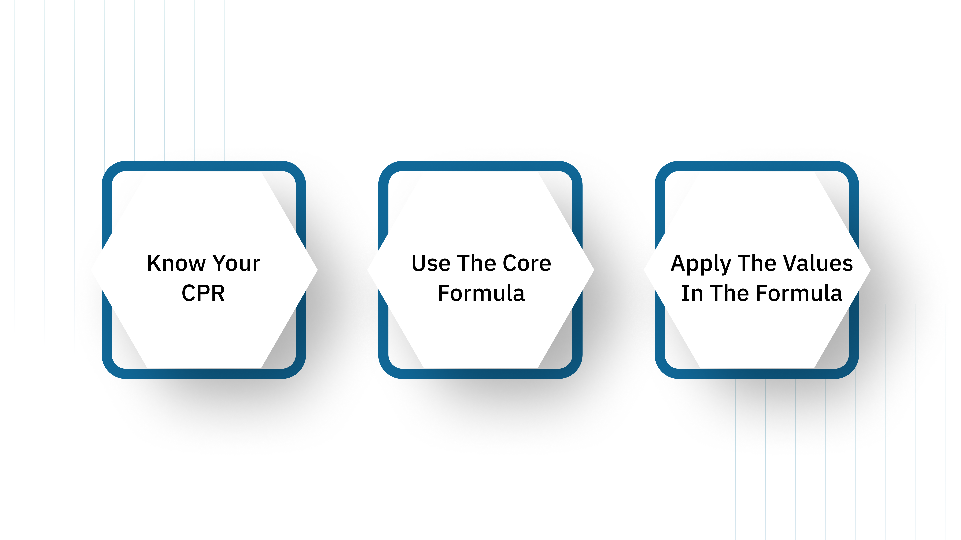
Step 1: Know Your CPR (Counts per Revolution)
CPR is the total number of usable counts the system receives after quadrature decoding.
If the encoder has:
PPR = 1000,
Then CPR = 4 × 1000 = 4000 counts.
Step 2: Use the Core Formula
For angular measurement, encoder resolution is calculated as:
Resolution (degrees per count) = 360° / CPR
CPR is used instead of PPR because most motion controllers read decoded counts, not raw pulses.
Step 3: Apply the Values in the Formula
Let’s calculate resolution using the CPR from above.
CPR = 4000 counts
Resolution = 360° / 4000
Resolution = 0.09° per count
A resolution of 0.09° per count allows the system to detect extremely small movements. In practice, this supports:
More stable positioning on CNC or robotic joints
Fewer micro-adjustment errors during high-speed operations
Lower scrap rate due to improved cut or alignment accuracy
More consistent throughput because motion feedback is smoother
This calculation helps engineers assess whether the encoder meets positional accuracy requirements for their machinery. Fine resolution reduces overshoot, improves alignment, and supports consistent throughput. Next, let's examine how different encoder types impact achievable precision and application suitability.
Types of Rotary Encoders and Their Effect on Resolution
Different encoder types handle signal generation and position reporting in unique ways, which directly affects achievable resolution, system accuracy, and overall equipment performance. Understanding these differences helps you choose and specify the right encoder for uptime, throughput, and lead-time stability.
Incremental Encoders
Incremental encoders generate pulses as the shaft rotates, providing relative position feedback. They do not store absolute position and rely on counting pulses from a reference point to determine movement.
Effect on Resolution:
Resolution depends directly on PPR and how you decode quadrature signals.
Suitable for applications where motion tracking over short distances is sufficient.
High-speed response enables precise motion control in dynamic systems.
Ideal use-case scenario: Conveyor belt speed monitoring in packaging lines.
Avoid when: Absolute position tracking is required after a power loss.
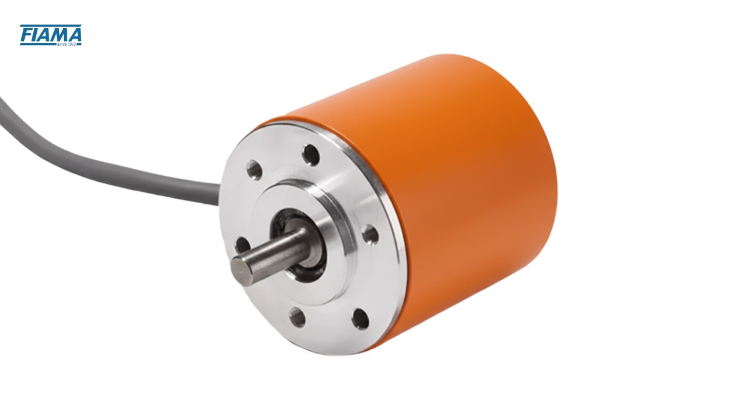
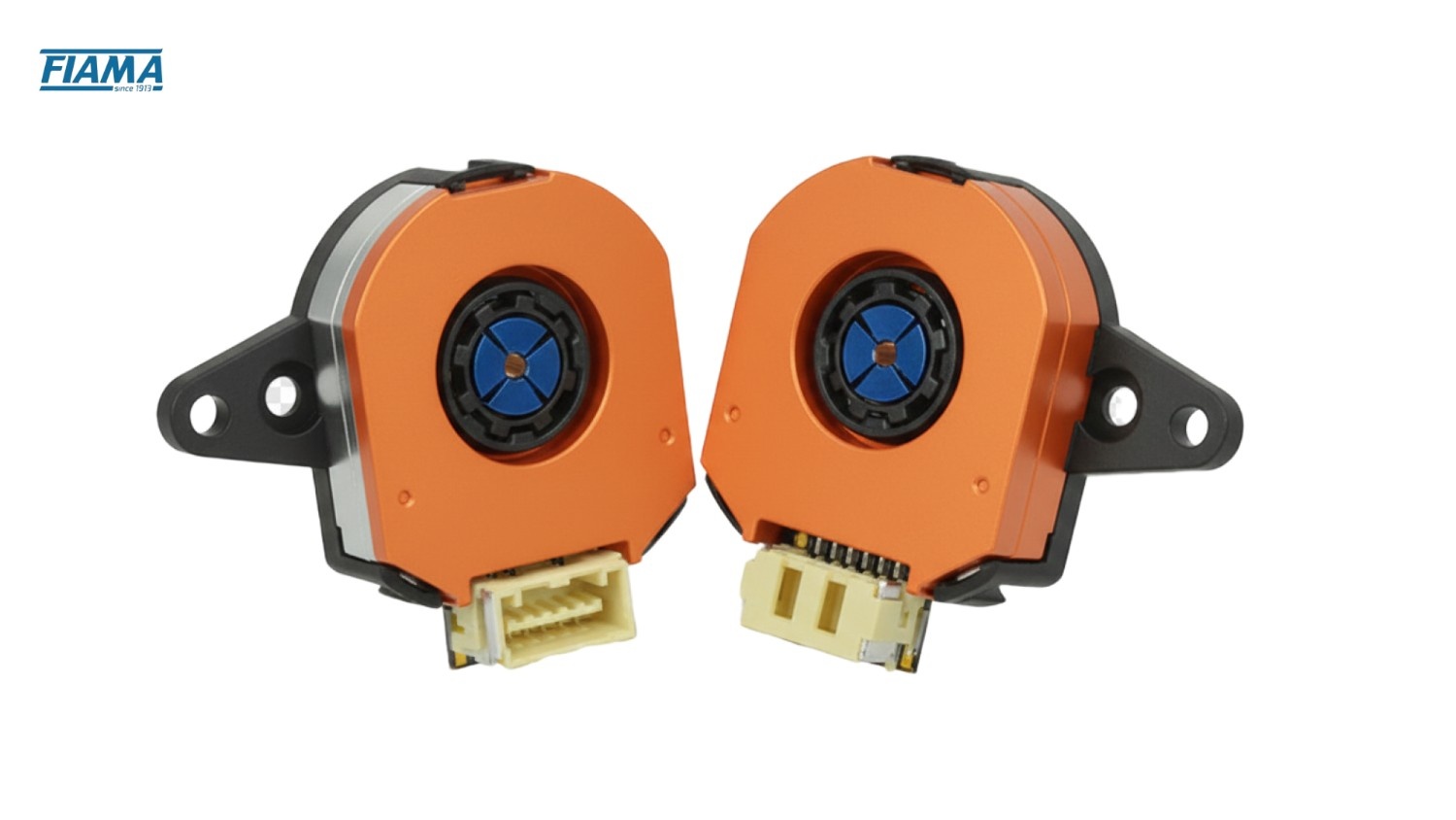
For example, Fiama’s EN hollow‑shaft encoder series(EN14, EN20, EN25, etc.) converts rotating motion into digital pulse signals (line driver outputs). These incremental encoders offer resolutions from 10 to 500 pulses/revolution (PPR).
Absolute Encoders
Absolute encoders provide a unique digital code for each shaft position, maintaining position information even after power interruptions. They are available in single-turn and multi-turn configurations.
Effect on Resolution:
Resolution is fixed and defined by the encoder’s bit count.
Multi-turn encoders allow measurement of multiple rotations without losing position.
High-resolution models support micro-positioning in precision machinery.
Ideal use-case scenario: CNC milling machines where exact position recovery after shutdown is critical.
Avoid when: Cost constraints make high-resolution absolute encoders impractical.
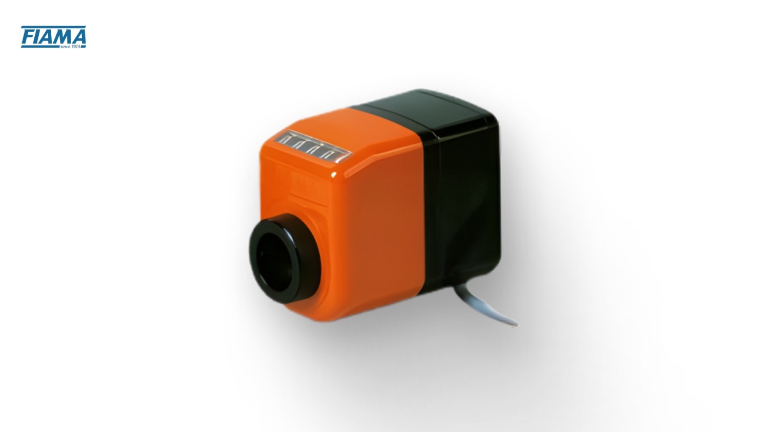
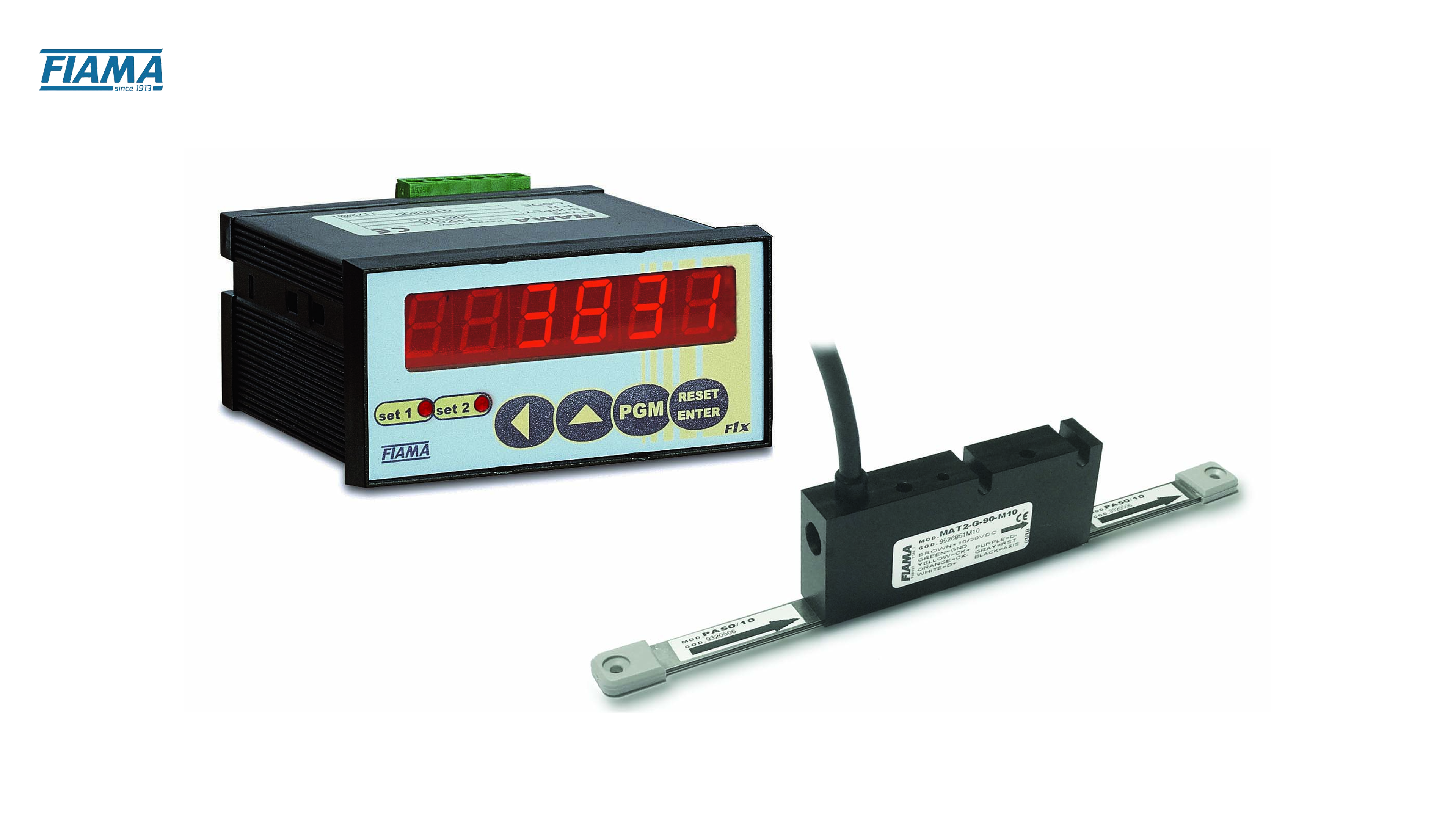
For example, Fiama’s MAT magnetic absolute encoder supports linear (or rotary via magnetic band/ring) applications with SSI output,
Magnetic Encoders
Magnetic encoders use a rotating magnet and sensors to generate pulses. They are robust against dust, oil, and harsh industrial environments.
Effect on Resolution:
Sensor density and PPR determine the encoder’s resolution.
Less sensitive to mechanical misalignment than optical encoders.
These encoders maintain reliable pulse output in vibration-heavy environments.
Ideal use-case scenario: Industrial robots operating in dusty or wet conditions.
Avoid when: Extremely high-resolution feedback (micro-degree accuracy) is required.
For example, Fiama’s magnetic encoder product lines, for both incremental and absolute, are designed to provide position feedback using magnetic sensor technology.
Optical Encoders
Optical encoders use a patterned disk and a light source to produce pulses. They offer high precision and repeatability in controlled environments.
Effect on Resolution:
It can achieve very fine resolution, supporting precise motion control.
Sensitive to dust, vibration, and contamination, which can reduce pulse accuracy.
High-frequency pulses deliver rapid motion feedback for automation systems.
Ideal use-case scenario: Packaging machines, robotic assembly, or metalworking equipment requiring high-precision positioning.
Avoid when: The environment is dusty, oily, or prone to mechanical shocks.
Capacitive Encoders
Capacitive encoders measure changes in capacitance across a patterned disk to generate position pulses. They provide a balance between robustness and precision.
Effect on Resolution:
The design allows these encoders to achieve moderate to high resolution.
More tolerant to contaminants than optical encoders but less robust than magnetic types.
Stable output supports medium-speed industrial applications.
Ideal use-case scenario: Packaging machinery where moderate resolution and reliability are required.
Avoid when: Ultra-high-speed or ultra-high-precision feedback is essential.
In the following section, let's consider factors that can influence pulse accuracy and overall system reliability.
How to Select the Right PPR and Resolution for Your Application?
Choosing the correct encoder PPR and resolution is essential for optimizing machine performance and reducing operational issues. Consider these key factors:
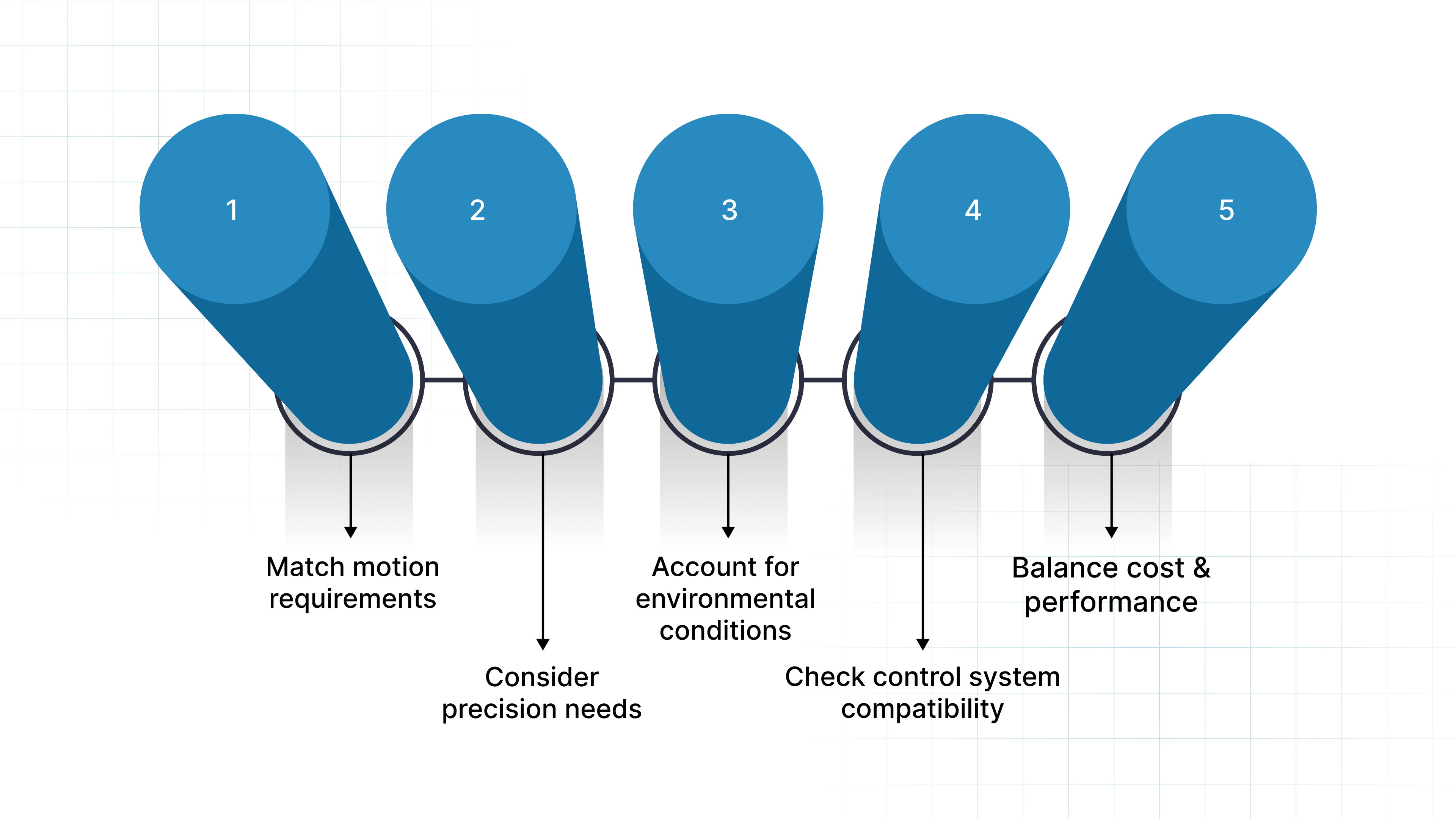
Match motion requirements: High-speed machinery benefits from higher PPR to ensure smooth and accurate movement without missing pulses.
Consider precision needs: Applications like CNC machines or robotics require higher resolution to maintain exact positioning and reduce errors.
Account for environmental conditions: Harsh, dusty, or high-temperature environments may favor magnetic encoders or robust designs to maintain signal integrity.
Check control system compatibility: Ensure the encoder’s pulse output and resolution align with your controller’s processing capability to avoid signal loss or miscounts.
Balance cost and performance: Selecting an encoder with appropriate PPR and resolution helps optimize production efficiency without unnecessary expense.
A well-chosen PPR and resolution ensure consistent throughput, minimized downtime, and support cost-effective operations. Next, let’s look at the pulse issues that engineers most frequently encounter.
Common Challenges With Encoder Pulses
Even with high-quality encoders, operational challenges can affect pulse accuracy and system performance. Key issues include:
Pulse Loss at High Speeds: When machinery operates at high speeds, the control system may fail to register every pulse. This can lead to missed position counts, reduced motion accuracy, and potential downtime if not addressed.
Signal Jitter and Electrical Noise: Interference from nearby motors, drives, or long cables can introduce inconsistencies in pulse signals. This may result in erratic motion, positioning errors, and increased scrap rates in precision processes.
Mechanical Wear and Misalignment: Over time, encoders with moving components may experience shaft wear or coupling issues. Even minor misalignment can distort pulses, affecting repeatability and leading to equipment inefficiency.
Environmental Factors: Dust, humidity, temperature fluctuations, and vibrations can compromise encoder signal integrity, especially in optical or delicate encoders. Ensuring robust installation and choosing the right encoder type maintains pulse accuracy.
Compatibility Issues with Control Systems: If the encoder’s resolution or signal type exceeds the controller’s processing capabilities, pulses may be miscounted or ignored. This affects position tracking, throughput, and overall production efficiency.
Addressing these challenges proactively through proper selection, installation, and maintenance protects equipment uptime and throughput.
How Fiama Supports High-Precision Rotary Encoder Applications?
As a distributor and manufacturer with over 100 years of experience, specializing in mechanical, electrical, and electro-mechanical measurement & control instrumentation, Fiama offers components suited for high‑precision and demanding industrial applications.
Here’s how we can help you:
Custom Stroke Lengths and Encoder Variants: Fiama offers tailored encoder solutions, including adjustable stroke lengths and specialized variants to match unique machinery requirements, supporting seamless integration in food, packaging, and automation equipment.
Robust Metal Housings and Materials: Designed for industrial environments, Fiama encoders feature durable metal housings and high-grade materials that withstand vibration, dust, and environmental stress, enhancing long-term operational stability.
Comprehensive OEM Engineering Support: Degreed engineers with application expertise provide hands-on assistance for specifying, installing, and calibrating encoders, ensuring machinery operates efficiently while minimizing trial-and-error adjustments.
In-House R&D and Manufacturing in Italy: Full control over the production process allows Fiama to offer consistent quality, rapid customization, and precise compliance with ISO 9001:2008 standards, directly supporting high-accuracy measurement and control requirements.
End-to-End Application Expertise via Edmar Metric LLC: In the Americas, Fiama’s exclusive partner provides application guidance, installation support, and technical assistance for optimized encoder deployment.
By choosing encoders from Fiama, industrial operators can reduce downtime, improve yield, and maintain consistent throughput in high-speed automation environments.
Conclusion
Understanding rotary encoder pulses, PPR, CPR, and resolution is vital for modern industrial operations. Correct specification and implementation help reduce downtime, improve yield, and stabilize lead times across automation, packaging, and CNC machinery.
Selecting the right encoder type and resolution for your application requires careful consideration of motion requirements, environmental conditions, and system compatibility. Working with a knowledgeable partner like Fiama ensures access to high-quality, customizable solutions that support your operational goals.
For guidance on selecting encoders tailored to your industrial application, contact us today to ensure optimal system performance and reliable production outcomes.
FAQs
How do I determine the required PPR for a specific application, such as linear motion measurement?
Determine the required PPR by assessing the desired measurement accuracy, mechanical system resolution, and motion speed. Higher precision applications or fine linear motion require encoders with higher PPR to capture small movements without introducing error or aliasing.
How does a higher PPR affect the precision of the encoder?
A higher PPR increases the number of pulses per revolution, allowing the encoder to detect smaller angular changes. This improves measurement resolution, providing finer position feedback and smoother control in motion systems, particularly in applications like robotics, CNC machines, and precision automation.
What role do encoder output channels (A, B, Z) play in pulse generation and resolution?
Channels A and B provide quadrature signals for direction and incremental position detection, while channel Z generates a reference pulse per revolution for homing or zeroing. Together, they enable precise motion tracking, directional awareness, and synchronization, enhancing overall encoder accuracy.
How do you calculate the frequency response of a rotary encoder based on PPR and shaft speed?
Frequency response (Hz) is calculated as:
Frequency = PPR × Shaft Speed (revolutions per second).
This indicates the maximum pulse rate the encoder can output, which helps ensure compatibility with the motion controller and avoids signal loss at high speeds.
What happens if the encoder resolution exceeds the maximum supported pulses per revolution?
Exceeding the maximum PPR can cause missed pulses, signal distortion, or inaccurate position feedback. The system may fail to register all movements, leading to errors in motion control, reduced performance, and potential mechanical issues in high-speed or high-precision applications.