Introduction
Shaft couplings are foundational components in virtually every rotating machinery system—from motors and pumps to conveyors, compressors, and CNC equipment. Choosing the wrong type leads to premature bearing failure, costly unplanned downtime, and reduced system efficiency. Research shows that improper coupling selection is among the leading causes of premature equipment failure, with excessive misalignment and torque overload accounting for the majority of coupling-related breakdowns.
Understanding the differences between coupling types is the most direct way to avoid those failures. This guide breaks down the two primary categories—rigid and flexible—covers the most common types within each, and walks through the key factors that determine the right fit for a given application.
Key Takeaways
- Shaft couplings connect rotating shafts to transmit torque while accommodating misalignment and protecting equipment from shock
- Rigid couplings suit perfectly aligned, precision-critical applications; flexible couplings handle misalignment and vibration
- Rigid coupling types include sleeve, flange, split clamp, and spline designs
- Flexible options cover jaw, gear, disc, and beam couplings — each suited to different load and misalignment conditions
- Correct selection comes down to torque, alignment, speed, environment, and maintenance access — not habit
- Wrong selection accelerates wear, creates system vibration, and causes unexpected failure
What Are Shaft Couplings?
Shaft couplings are mechanical devices that connect two rotating shafts—a driving shaft powered by a motor or engine, and a driven shaft connected to a pump, gearbox, or other load—to transfer torque and rotational motion between them.
Three core functions all couplings serve:
- Power transmission — Delivers torque from driver to driven equipment with minimal energy loss
- Misalignment accommodation — Compensates for parallel (radial), angular, and axial shaft offset
- Shock and vibration protection — Dampens vibration and absorbs shock loads that would otherwise damage bearings and seals
Of these three, misalignment tolerance is the one most often underestimated in real installations. Even minor unaddressed misalignment—as little as 0.5° angular or 0.010" parallel offset—causes accelerated wear on bearings, seals, and the coupling itself. Studies confirm misalignment is the primary failure mode in coupling applications. The coupling type you choose determines whether your system handles real-world installation imperfections or wears out prematurely because of them.
Rigid vs. Flexible: Understanding the Two Primary Categories
All shaft couplings fall into one of two families: rigid and flexible.
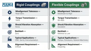
Rigid couplings create a solid, immovable connection between shafts—transmitting torque with zero energy loss through flexing, but requiring near-perfect shaft alignment to function correctly. They deliver maximum torque efficiency and precision positioning, making them ideal for automation, CNC, and instrumentation applications where backlash cannot be tolerated.
Flexible couplings introduce a compliant element (elastomeric, metallic, or mechanical) that tolerates misalignment, absorbs shock, and dampens vibration. This protects connected equipment from real-world installation imperfections, though the tradeoff is minor backlash or torsional compliance that some precision applications cannot accept.
| Rigid Couplings | Flexible Couplings | |
|---|---|---|
| Misalignment Tolerance | Near-zero | Moderate (angular, parallel, axial) |
| Torque Transmission | 100% — no energy loss | Slight loss through compliant element |
| Shock/Vibration Absorption | None | Yes |
| Backlash | Zero (if properly aligned) | Minor (type-dependent) |
| Typical Applications | CNC, servo drives, instrumentation | Pumps, conveyors, general industry |
| Alignment Requirement | Critical | Forgiving |
Neither category is universally superior. The right choice depends on alignment conditions, load characteristics, speed, and how sensitive the connected equipment is to backlash or torsional variation. In practice, the same facility often runs rigid couplings on servo-driven axes and flexible couplings on motor-to-pump connections — each doing the job the other cannot.
Types of Rigid Shaft Couplings
Rigid couplings work best when shaft alignment is controlled, precision torque transfer is required, and backlash cannot be tolerated. They're the standard choice in automation, CNC, robotics, and instrumentation applications.
Sleeve (Muff) Coupling
The simplest rigid coupling: a hollow cylindrical sleeve that slides over and connects two shaft ends, transmitting torque via keys fitted into matching keyways. It's the most compact and cost-effective rigid option, suited for light-to-medium torque applications with well-aligned shafts and limited installation space—such as pumps, fans, and small conveyors.
The tradeoff is strict: zero misalignment tolerance and no installation flexibility without axial shaft access.
Flange Coupling
Two flanged hubs—each keyed to a shaft—are bolted together face-to-face. The spigot-and-recess alignment feature ensures coaxial positioning. Subtypes include unprotected (exposed bolts), protected (enclosed bolts for hazardous environments), and marine (tapered bolts for high-vibration resistance). Best suited for heavy-duty industrial applications requiring high torque transmission, such as large pumps, compressors, and heavy rotating equipment.
Its bolt pattern delivers high torque capacity and steady-load reliability, but adds assembly complexity and weight — and demands precise shaft alignment before installation.
Split Clamp Coupling
A rigid coupling that splits into two or three sections that clamp around the shaft without requiring axial access—meaning the coupling can be installed and removed without disturbing adjacent components or removing shaft ends. Internally keyed to each shaft for torsional alignment. Used widely in manufacturing lines, conveyor systems, and process machinery where maintenance access is limited.
This design cuts maintenance downtime significantly. The cost is slightly higher than a sleeve coupling, and clamping force must be carefully torqued to avoid shaft damage.
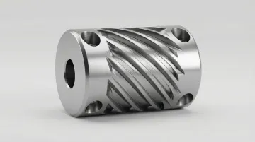
Spline Coupling
A high-precision coupling featuring internal teeth (splines) on the sleeve that mesh with external splines on the shaft, distributing torque uniformly across multiple contact points without a separate key. FEA studies confirm that splines eliminate stress concentrations that cause keyway crack propagation, while providing axial mobility under load. Common in gearboxes, automotive transmissions, servo drives, and industrial automation systems.
Spline couplings offer superior torque distribution and minimal backlash, handling radial and angular micro-misalignments better than keyed designs. The tradeoff is higher manufacturing precision — and a corresponding price premium over keyed alternatives.
Rigid Coupling Comparison
| Coupling Type | Best Use Case | Key Strength | Key Limitation |
|---|---|---|---|
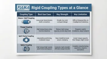
| Sleeve (Muff) | Pumps, fans, small conveyors | Lowest cost and complexity | Zero misalignment tolerance; needs axial access |
| Flange | Large pumps, compressors, heavy equipment | High torque capacity, reliable under load | Heavy; requires precise alignment before assembly |
| Split Clamp | Conveyors, process lines with limited access | Install/remove without axial access | Higher cost; clamping torque must be precise |
| Spline | Gearboxes, servo drives, automotive transmissions | Best torque distribution, minimal backlash | Most expensive; tighter manufacturing tolerances |
Types of Flexible Shaft Couplings
Flexible couplings are the practical choice when perfect shaft alignment is difficult to guarantee, when systems experience vibration or shock, or when thermal expansion is expected to shift shaft positions during operation.
They're classified by the source of their flexibility:
- Elastomeric — compression or shear of a polymer element
- Mechanical — sliding or rolling contact between metal components
- Metallic element — bending of thin steel discs or diaphragms
| Coupling Type | Best Use Case | Misalignment Tolerance | Lubrication Required |
|---|---|---|---|
| Jaw (Elastomeric) | Light industrial, food/beverage, pumps | Angular + parallel + axial | No |
| Gear | Heavy industrial, mills, high-power drives | Up to 1.5° angular per mesh | Yes |
| Disc | Servo systems, precision positioning, high speed | ~0.10° per disc pack | No |
| Beam (Helical) | Robotics, encoders, medical instruments | Up to 7° angular (double-beam) | No |
Jaw (Elastomeric) Coupling
Two interlocking jaw hubs grip an elastomeric "spider" insert that transmits torque while absorbing shock and vibration. The design accommodates angular, parallel, and axial misalignment, requires no lubrication, and resists dirt, moisture, and oil contamination. It's widely used in motion control, light industrial machinery, pumps, and food/beverage processing where low maintenance matters.
The fail-safe behavior is a practical advantage: the spider degrades before connected equipment does, giving operators a warning before catastrophic failure. The tradeoff is temperature sensitivity — NBR spiders operate from -40° to 212°F, urethane from -30° to 160°F — and spider durometer directly affects stiffness and torque capacity, so material selection requires care.
Gear Coupling
Where jaw couplings handle light to moderate loads, gear couplings step up to the heaviest industrial drives. External gear teeth on the hubs mesh with internal teeth on flanged sleeves, transmitting high torque while accommodating limited angular and parallel misalignment through tooth clearances. Standard sizes typically allow 1.5° angular misalignment per gear mesh, making them common in steel mills, paper mills, and high-power pump and compressor systems.
The strength is torque density — few flexible couplings move more power through a given shaft diameter. The constraint is maintenance: gear couplings require regular lubrication, generate heat and accelerated wear if misalignment runs high, and aren't appropriate where zero backlash is required.
Disc Coupling
Shifting from mechanical to metallic-element designs, disc couplings use thin flexible steel discs to transmit torque between flanged hubs. The discs flex to absorb misalignment with no sliding contact — meaning no lubrication, no wear particles, and long service life. Torsional rigidity makes them a natural fit for servo motor systems, precision positioning equipment, blowers, and compressors. Balanced designs run smoothly up to 10,000 RPM.
The limitation is misalignment tolerance: disc couplings typically allow only 0.10° per disc pack. Axial overload is a real risk — excessive misalignment drives rapid fatigue failure in the disc packs, so installation alignment needs to be tight.
Beam (Helical) Coupling
Beam couplings take a different approach entirely: a single piece of machined metal with helical cuts that create a flexible beam structure. One-piece construction means zero backlash — there are no inserts, no assembly parts to loosen or wear, and no elastomers to degrade at temperature. Single-beam designs accommodate up to 5° angular misalignment; double-beam variants reach 7°, with multi-beam variants trading some misalignment capacity for higher torsional stiffness.
They're the go-to choice for robotics, encoders, light-duty motion control, and medical instruments — applications where precision and compact size matter more than high torque. The tradeoff: helical cuts reduce axial stiffness, which creates problems in vertically mounted or high-axial-load systems.
How to Choose the Right Shaft Coupling for Your Application
The "right" coupling is the one that matches the actual operating conditions of your application—not the most familiar, most commonly available, or most heavily marketed option. FIAMA's application specialists are degreed engineers, not commissioned salespeople—which means coupling recommendations are driven by technical fit, not sales quotas.
Torque and Speed Requirements
The coupling must be rated for the peak torque of the drive system (not just the nominal torque) and the maximum RPM. Applying a service factor of 1.25–2.5× nominal torque depending on shock and load variability is standard engineering practice and should be factored into sizing. Under-sizing by using nominal torque instead of peak torque with service factor is one of the most common selection mistakes.
Misalignment Type and Degree
Engineers must identify whether the dominant misalignment is angular, parallel, or axial—and quantify it. Rigid couplings require near-zero misalignment; elastomeric couplings handle moderate misalignment well; gear and universal-joint couplings are suited for larger angular offsets. Misrepresenting or ignoring alignment tolerances is the most common cause of premature coupling failure—and it's a problem that compounds quickly in the wrong environment.
Operating Environment and Lubrication Requirements
Environmental factors—temperature range, contamination exposure (dust, chemicals, moisture), food-grade compliance needs—significantly narrow the coupling options. Gear couplings require lubrication and are ill-suited for food-processing environments; jaw and disc couplings require none.
In pharmaceutical or semiconductor settings, zero-contamination elastomers or fully metallic designs may be required. Food contact materials must comply with FDA CFR Title 21 and EU Regulation 1935/2004.
Common Selection Mistakes to Avoid
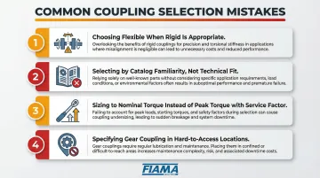
Four critical pitfalls:
- Choosing a flexible coupling when alignment is controllable and a rigid coupling would perform better
- Selecting based on catalog familiarity rather than technical fit
- Sizing to nominal torque instead of peak torque with service factor applied
- Specifying a gear coupling in a hard-to-access location where lubrication maintenance will be skipped
Conclusion
Shaft couplings are not interchangeable. The choice between rigid and flexible types — and among the many subtypes within each category — directly determines whether a rotating system operates reliably, efficiently, and with minimal maintenance over its design life.
Proper coupling selection is an engineering decision that deserves engineering input. If you're unsure about the right coupling for your application, FIAMA's team of degreed engineers can help. They're not commissioned and carry no quotas, so their guidance focuses on what works for your system.
Frequently Asked Questions
What are the different types of shaft couplings?
The two primary categories are rigid (for precision-aligned systems) and flexible (for misalignment tolerance). Common rigid types include sleeve, flange, split clamp, and spline; common flexible types include jaw, gear, disc, and beam/helical couplings. The right type depends on your specific torque, alignment, and operating conditions.
What is the difference between rigid and flexible shaft couplings?
Rigid couplings create a fixed, zero-flex connection best for precision-aligned systems requiring zero backlash. Flexible couplings use elastomeric, metallic, or mechanical elements to accommodate misalignment, absorb shock, and dampen vibration—trading some precision for easier installation and equipment protection.
Which shaft coupling is best for high-speed applications?
Disc couplings and diaphragm couplings are typically preferred for high-speed precision applications due to their torsional rigidity, zero backlash, and lubrication-free design. Beam/helical couplings suit lighter high-speed motion control needs. Gear couplings can handle high torque at moderate speed but require regular lubrication.
Can shaft couplings connect shafts of different diameters?
Yes. Many designs—particularly split clamp, spline, and certain flexible types—are available with different bore sizes on each hub to connect shafts of unequal diameters. Shaft adapters can also bridge dimensional differences when a standard coupling won't reach.
How do I know if a shaft coupling is failing?
Watch for these warning signs:
- Unusual vibration or noise during operation
- Visible cracking or wear on elastomeric elements
- Heat generation near the coupling
- Recurring bearing failures in connected equipment
Any of these indicate the coupling is no longer functioning as designed.
Do flexible shaft couplings require regular maintenance?
It depends on the type. Elastomeric (jaw) and metallic-element (disc/beam) couplings are generally maintenance-free with no lubrication needed. Mechanically flexible types such as gear and grid couplings require regular lubrication and periodic inspection.