When a production line needs higher torque, tighter speed control, or a more stable load response, the issue often traces back to the gearbox. Many plant heads and engineering teams run into performance gaps because the planetary gearbox gear ratio was assumed, estimated, or taken from a generic datasheet. These often lead to problems like inconsistent throughput, higher scrap, and avoidable downtime during high-load cycles.
Accurate planetary gearbox gear ratio calculation addresses these challenges effectively. It ensures that torque and speed are optimized for each application, protecting components and improving yield stability. With the industrial planetary gearbox market set to reach USD 5.64 billion by 2033, choosing the right ratio has become essential.
By understanding how to calculate and select the right ratios, engineers and procurement managers can make informed decisions that reduce system stress, lower the cost per unit, and extend the lifespan of vital equipment. This guide provides a structured approach with step-by-step instructions, examples, and insights to help you calculate planetary gearbox gear ratios with clarity.
Key Takeaways:
Understanding how the planetary gearbox works and how its core components interact is crucial for calculating accurate gear ratios that ensure optimal torque and speed.
Key terms such as gear teeth, reduction ratio, torque multiplication, and backlash directly influence gearbox performance under industrial load conditions.
Following a structured, step-by-step calculation process, considering input/output members, fixed components, and multi-stage configurations, reduces errors and ensures consistent production quality.
Using tools, simulations, and careful validation, while avoiding common mistakes, ensures the gearbox meets operational requirements and extends equipment lifespan.
What is the Planetary Gearbox?
A planetary gearbox, also called an epicyclic gearbox, distributes power through a set of gears arranged around a central sun gear. This design allows multiple planet gears to rotate around the sun gear while engaging with the outer ring gear. Compared to traditional parallel shaft gearboxes, planetary gearboxes offer:
High torque density in a compact design
Even load distribution, reducing gear wear
High efficiency, supporting stable throughput
These characteristics make planetary gearboxes suitable for industries ranging from food and packaging to metal processing and automation systems.
Core Components and Their Motion Relationship
A planetary gearbox consists of four main components:
Sun Gear: The central gear receives input power from the motor. It drives the planet gears and sets the initial speed and torque flow in the system.
Planet Gears: These gears orbit the sun gear while meshing with both the sun and ring gears. They evenly distribute load, increase torque capacity, and ensure smooth motion transfer.
Ring Gear: The outer gear surrounds the planet gears. Fixing or allowing it to rotate alters the gear ratio, changes output speed, and can even reverse rotation direction depending on the configuration.
Carrier: Holds the planet gears in place and transmits torque to the output shaft. The carrier’s motion depends on which component is fixed, affecting overall speed and torque multiplication.
The interaction of these components determines the gear ratio. For example, fixing the ring gear versus the sun gear changes how torque is multiplied and the speed at which the output shaft rotates. Properly understanding these relationships is essential for achieving precise planetary gearbox gear ratio calculations.
Next, let's understand the terms that define their function in gear ratio calculations.
Key Terms Used in Planetary Gear Ratio Calculation
Before calculating the planetary gearbox gear ratio, familiarize yourself with these terms:
Gear Teeth (Z): The number of teeth on sun, planet, and ring gears determines speed reduction and torque multiplication in the system. Accurate counting is essential for precise ratio calculation.
Input Gear: The gear connected to the power source (motor). Its speed and torque set the baseline for calculating output performance and overall gear ratio.
Output Gear: The gear delivering torque to the load. The combination of input speed, output speed, and gear arrangement defines system efficiency and performance.
Reduction Ratio: The ratio of input speed to output speed. It indicates how much the gearbox slows down the input while increasing torque, which directly affects throughput and machine load.
Torque Multiplication: How much the gearbox increases the input torque at the output. This is critical for handling heavy loads without overloading the motor.
Backlash: The clearance between meshing teeth that affects precision. Too much backlash can reduce torque consistency and impact repeatable motion in high-accuracy applications.
A clear understanding of these terms helps plant engineers and operations leaders assess gearbox suitability for applications, ensuring optimal yield and minimizing machine downtime.
In the next section, let's discuss the foundational principles that guide accurate ratio computation.
Fundamentals of Gear Ratio Calculation
The planetary gearbox gear ratio is influenced by which component is fixed and which is the input/output. Accurate calculations allow engineers to:
Predict torque output
Adjust speed for process requirements.
Reduce scrap rates caused by inconsistent machine performance.
Basic Gear Ratio Formula for Planetary Gearboxes
The general formula for a single-stage planetary gearbox is:
i=1+Zr/Zs
Where:
i = gear ratio
Zr = number of teeth on the ring gear
Zs = number of teeth on the sun gear
This formula assumes the sun gear is the input, the ring gear is fixed, and the planet carrier is the output. Using the formula correctly allows engineers to predict torque and speed changes without trial-and-error, reducing operational risk.
Example: If the sun gear has 20 teeth and the ring gear has 60 teeth:
i=1+60/20=4:1
This means output speed is one‑quarter of input speed; torque is roughly quadrupled (ignoring efficiency losses).
How Does Fixing Different Members Change the Ratio?
The gear ratio in a planetary gearbox depends on which component is fixed, which receives input, and which acts as output. Key configurations include:
Ring fixed, Sun input, Carrier output: Common configuration for high torque, low-speed applications.
Sun fixed, Ring input, Carrier output: Reverses torque and speed roles.
Carrier fixed, Sun input, Ring output: Often used to achieve intermediate speed ratios.
These options give planetary gearboxes their flexibility, enabling engineers to fine-tune speed, torque, and rotation direction based on system requirements.
In the next section, let's discuss the step-by-step calculation process to ensure accuracy.
Step-by-Step Method to Calculate Planetary Gear Ratio
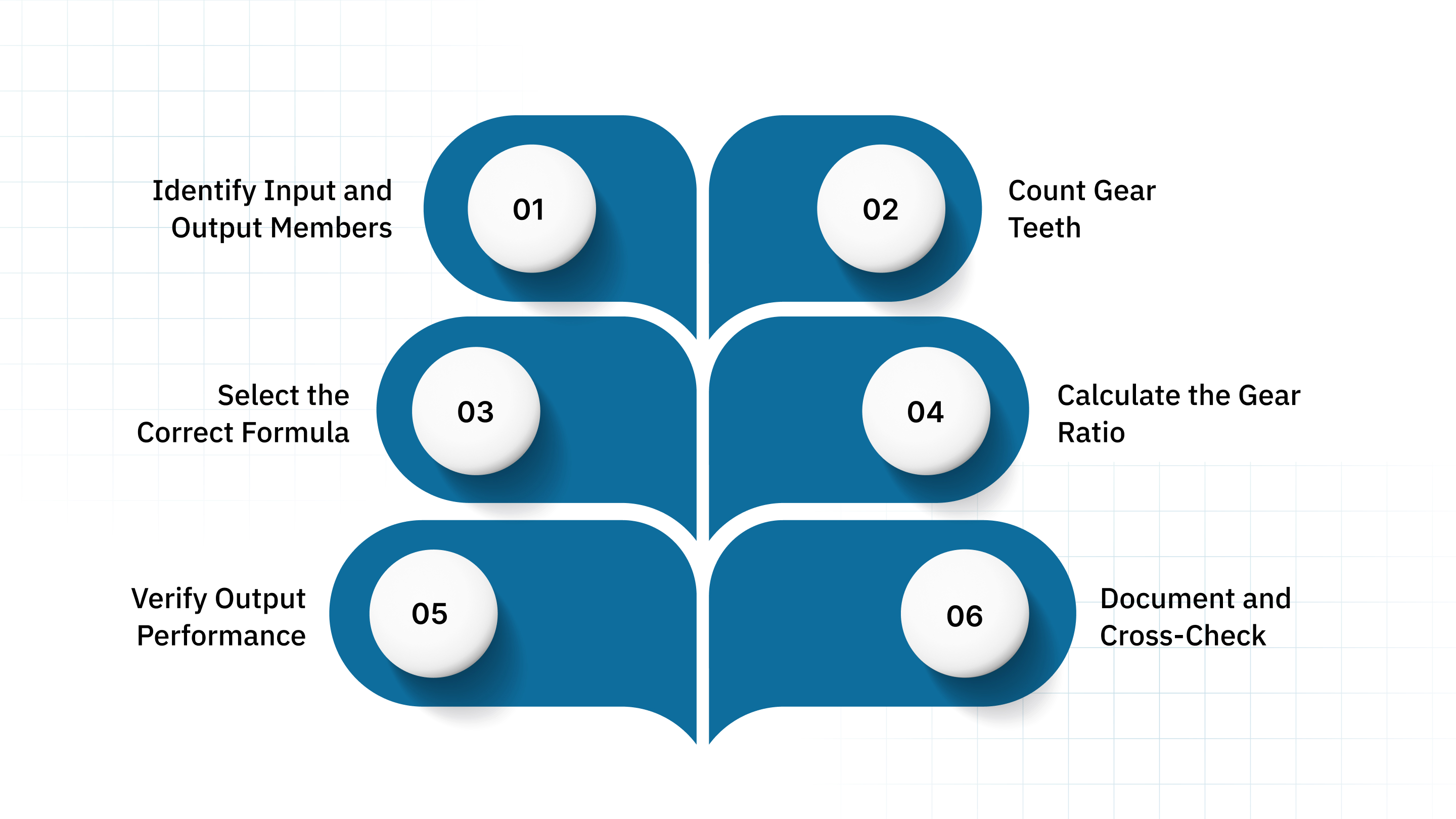
Calculating a planetary gearbox gear ratio doesn’t have to be complex. Breaking it into clear steps helps engineers avoid mistakes and ensures the output meets performance requirements. Here’s a step-by-step method:
Step 1: Identify Input and Output Members
Determine which component is connected to the motor (input) and which delivers torque to the load (output). The choice of input and output members influences which formula to apply and how the ratio will affect torque and speed.
Step 2: Count Gear Teeth
Obtain the number of teeth on the sun gear (Zs), ring gear (Zr), and planet gears (Zp). Accurate counts are essential because even a small error can significantly alter torque multiplication or speed reduction.
Step 3: Select the Correct Formula
Based on the member that is fixed (ring, sun, or carrier), apply the corresponding planetary gearbox formula:
Sun input, ring fixed, carrier output: i=1+Zr/Zs
Carrier fixed: Different formula for speed increase.
Sun fixed: Output direction reverses; adjust torque calculations accordingly.
Applying the correct formula ensures the calculation aligns with the gearbox’s physical configuration and prevents mistakes.
Step 4: Calculate the Gear Ratio
Apply the formula to determine the speed reduction and torque multiplication. This step quantifies how much the gearbox reduces speed and increases torque from input to output, allowing engineers to check alignment with machine specifications.
Step 5: Verify Output Performance
Compare the calculated torque and speed with the requirements of the load. Ensure the gearbox can handle the expected operational conditions, including peak torque, continuous load, and potential misalignment. Verifying performance at this stage helps prevent overloading and unplanned downtime.
Step 6: Document and Cross-Check
Record all calculations, assumptions, and gear specifications. Double-check tooth counts, formula application, and output values. This step minimizes errors and serves as a reference for future maintenance or system upgrades.
Following these steps reduces the risk of miscalculations, helps avoid equipment downtime, and ensures consistent production quality. Next, let's discuss how to calculate the ratio for multi-stage systems for higher reduction ratios.
Advanced Calculations for Multi-Stage Planetary Systems
Multi-stage planetary gearboxes connect several single-stage units in series. They are used when high reduction ratios are required in compact spaces. The overall gear ratio is the product of the individual stage ratios:
itotal=i1×i2×i3
For example, if Stage 1 has a 5:1 ratio and Stage 2 has a 4:1 ratio, the total reduction is 20:1.
Multi-stage calculations require careful attention to torque limits, efficiency losses, and component alignment. These calculations help maintain expected output performance under heavy industrial loads.
In the following section, let's explore the specialized tools and software required for precise validation.
Tools & Software used for Accurate Gear Ratio Calculations
Engineers often rely on digital tools to validate planetary gearbox gear ratio calculations, especially for multi-stage systems or application-specific torque requirements. These tools help reduce manual errors, improve design accuracy, and accelerate decision-making.
Spreadsheet-Based Calculators (Excel, Google Sheets): Useful for quick, repeatable calculations where you can plug in gear teeth, fixed members, and desired output. They allow engineers to model single or multi-stage ratios and document assumptions for future audits.
Online Planetary Gear Ratio Calculators: Commonly used for standard sun–planet–ring configurations. They deliver instant ratio estimates and help validate preliminary designs before deeper engineering work begins.
CAD and Simulation Platforms (SolidWorks, Fusion 360): These tools allow 3D modeling of gear geometry and simulate how gears interact under dynamic loads. Engineers use them to check mesh accuracy, clearances, and thermal or stress effects that may influence ratio consistency.
Specialized Gear Design Software (KISSsoft, MITCalc): Designed for advanced gearbox engineering. They assess load distribution, tooth bending forces, material stresses, and efficiency losses, making essential checks before finalizing a gearbox for production equipment.
Manufacturer-Supported Tools and Configurators: Some suppliers provide digital configurators that help match gear ratio, torque rating, and mounting style to specific machine requirements. These tools streamline selection and reduce calculation errors by using validated component data.
In the next section, let’s discuss common pitfalls that can compromise accuracy,
Common Mistakes to Avoid When Calculating Planetary Gear Ratios
Even experienced engineers can run into errors when calculating a planetary gearbox gear ratio. Common mistakes include:
Wrong fixed member selection: This changes the entire planetary gearbox gear ratio and can lead to incorrect torque or speed output, causing performance issues in production equipment.
Incorrect gear teeth count: Using assumed or outdated tooth numbers leads to inaccurate ratios, poor load distribution, and potential long-term reliability problems.
Ignoring efficiency losses: Not accounting for losses across single or multi-stage systems results in overestimated torque output and inconsistent machine performance.
Overlooking mechanical limits: Exceeding bearing load capacity or material strength increases wear, heat generation, and alignment issues under continuous operation.
Motor–gearbox mismatch: Failing to check input speed, torque curve, and duty cycle increases the likelihood of overheating, vibration, and unstable speed control.
Poor lubrication or maintenance: Inadequate lubrication accelerates wear, increases backlash, and reduces long-term accuracy of the planetary gearbox gear ratio.
Avoiding these mistakes improves system uptime and extends component life, directly impacting operational KPIs.
How Fiama Simplifies Gear Ratio Selection for Planetary Gearboxes?

Fiama provides both engineering support and high-quality components to help clients select the right planetary gearbox. With Italian-made products and over 100 years of design and manufacturing experience, Fiama delivers:
Engineering-Driven Support: Fiama’s degreed engineers work directly with machine builders to review load conditions, duty cycles, and mechanical constraints. This helps teams select a planetary gearbox gear ratio that aligns with real operating demands, not just theoretical calculations.
Expertise from a Focused Product Line: By carrying only a limited number of product families, Fiama provides deeper technical guidance. Engineers get clear recommendations on ratio ranges, torque paths, and configuration options without sifting through overwhelming catalog choices.
Custom Variants Built in Parma: Fiama can supply modified housings, mounting styles, or internal configurations when OEMs need ratios or layouts that standard units don’t support. These adjustments help reduce retrofit time and improve equipment integration.
Durable Mechanical Construction: Their gear solutions use stable metal housings and controlled manufacturing processes, giving engineers predictable mechanical behavior over long operating periods, especially useful for multi-shift plants.
Local Support Through Edmar Metric LLC: With a dedicated U.S. partner, teams get quick responses to technical questions, component selection, and documentation needs. This helps avoid delays during design reviews or maintenance planning.
By utilizing Fiama’s expertise, engineers can focus on process reliability, throughput stability, and cost per unit reduction while ensuring the planetary gearbox fits their operational needs.
Conclusion
Accurate planetary gearbox gear ratio calculation is essential for reliable machine performance. Correct ratios directly impact torque, speed, and efficiency, helping operations leaders reduce downtime, improve yield, and maintain consistent throughput. Following a structured, step-by-step method minimizes errors and supports effective multi-stage system design.
Fiama’s experience and support further simplify gearbox selection, ensuring high-quality, application-specific solutions. Engineers and plant managers looking to optimize performance can reach out to us today for guidance and tailored planetary gearbox solutions.
FAQs
How is the gear ratio defined in a planetary gearbox?
The gear ratio in a planetary gearbox is the ratio of input speed to output speed. It determines how torque and speed are distributed between the sun, planet, and ring gears, influencing overall performance and efficiency of the gearbox.
How do the speeds of the sun gear, ring gear, and carrier relate to the gear ratio?
The gear ratio depends on the relative speeds of the sun, ring, and carrier. The motion of one gear affects the others, and their speed relationship is determined by gear geometry and which component is fixed, driving the output torque and rotational speed.
How do angular velocities of different gears factor into gear ratio calculations?
Angular velocities define how fast each gear rotates. By comparing these velocities, you can calculate the gear ratio, as the ratio of input to output speeds depends directly on the angular velocity of the sun, planet, and ring gears in the planetary system.
What practical applications require precise planetary gearbox gear ratio calculations?
Industries like robotics, aerospace, automotive, and industrial machinery rely on precise gear ratio calculations. Accurate ratios ensure proper torque transmission, smooth motion, efficiency, and reliability in applications like robotic arms, electric vehicles, wind turbines, and conveyor systems.
What is the relationship between the number of teeth on the sun, planet, and ring gears?
The number of teeth on the sun, planet, and ring gears determines the gear ratio and proper meshing. Typically, the ring gear teeth equal the sum of the sun and twice the planet gear teeth, ensuring smooth rotation and balanced torque distribution.